New Lockheed LIGHTWEIGHT SERVO UNIT
Page 41

If you've noticed an error in this article please click here to report it so we can fix it.
Vacuum-hydraulic Principle Provides for More-direct Brake Action.
SIMPLE to install, light in weight, easy to maintain and low initial cost: these represent outstanding features of a new brake servo unit for medium-weight commercial vehicles which will be exhibited at the forthcoming Commercial Motor Show at Earls Court. Known as the Hydrovac servo brake unit, nearly 2,000,000 are already in use abroad, and the system, redesigned to meet conditions in this country, is now made wholly in the Lockheed factory at Leamington Spa.
The new vacuum-hydraulic unit furnishes power for brake actuation on commercial vehicles equipped with hydraulically operated brakes. A vacuum power-cylinder and control valve are combined with a hydraulic slave-cylinder working on a principle which gives certain advantages over the usual vacuum servo. By adding the latent vacuum power of the engine manifold to the hydraulic system, the new unit ensures a smooth, progressive and powerful retardation which calls for the minimum of effort from the driver.
A vacuum servo usually obtains its power from atmospheric pressure acting on one side of a piston, the air on the other side being partially exhausted. This provides a difference of pressure on the opposite sides of the piston to enable useful work to be done. Before the brakes are applied through the conventional servo, atmospheric pressure is present on both sides of the piston, and the servo action is obtained by partially exhausting the working chamber.
The Hydrovac unit reverses this process, there being a partial vacuum on both sides of the servo system. With the application of the brakes. it is brought into action by admitting air to one side only. This affords the advantage that the servo itself forms a vacuum reservoir, and the normal vacuum tank may be reduced in size or, in certain cases, may be dispensed with. • Because the air has only a short distance to travel, the braking action is much more rapid. Air has to be admitted only in proportion to the working stroke, therefore it is economical in a vacuum, showing a saving of 25-50 per cent. over conventional units. It is manufactured in one size only and is generally suitable for any vehicle of 6-11 tons gross weight, fitted with hydraulic brakes.
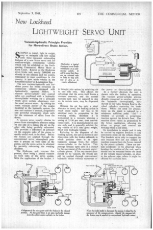
Referring to the diagrams of the braking system, the unit is shown in one illustration with the brakes released, in which position there is an open hydraulic passage from Abe vehicle master-cylinder to the brakes. This passage remains open until it is closed' by the movement of the vacuum powercylinder piston. If for any reason there should be no vacuum, the brakes can still be applied through conventional hydraulic means without movement of the power or slave-cylinder pistons.
In a further diagram the unit is shown with the brakes in operation. The vacuum power-cylinder pistons. directly connected to another piston in the hydraulic slave-cylinder, have moved to the right, forcing fluid to the wheel cylinders operating the brake shoes. Whilst the need for physical force on the pedal is reduced to a minimum, sufficient pedal feel" is retained to provide a progressive reaction against the driver's foot. This reaction force varies in proportion to the brake application, allowing the driver to gauge and control the braking effort at all times.
Its installation is simple and it may be carried by support brackets at any convenient point on the vehicle chassis. The brackets serve only to support the unit because they are not subject to reaction stresses from the forces exerted by the power cylinder. There are certain conditions to be observed when locating the position of the unit, and it should not be mounted below the level of the vehicle master-cylinder, or close to the exhaust pipe, where it _might be affected by excessive heat.


