


Gully-emptier with Constant Weight Distribution
Page 40
If you've noticed an error in this article please click here to report it so we can fix it.
UNIFORM distribution of weight and more convenient pipe locations are the chief features of an improved gully-emptier described in patent No. 469,489 by Deighton's Patent Flue and Tube Co., Ltd., and J. Ridealgh, both of Vulcan Works, Hunalet, Leeds. Hitherto, these vehicles have carried a two-part tank, one section of which is filled with water or disinfectant on the outward journey, the other section being empty, whilst on the return the position is reversed. This has brought problems of weight distribution which the present patent is an attempt to solve.
The main improvement is the use of a cylindrical tank containing an inner concentric shell (shown dotted) for the reception of the sludge, the water being carried in the outer space. By this means, not only is the load, uniformly distributed whether. the tanks be full or empty, but also the pipe connections can be attached at any desired point in the length Of the vehicle.
A Spring Requiring No Shackles.
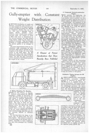
FROM H. Van Doome, of Deume, Holland, comes patent No. 469,393 describing a design of leaf-spring for uhich the claim is made that an extensible fixing is rendered unnecessary. The sole point cif the design is the special curvature of the main leaf or leaves. The eyes of these are positiOned so that their axes are a certain distance above (or below) the blade. Consequently, when the spring is loaded, there is a partial unwrapping of the eye which compensates for the usual foreshortening, and the need for one Movable shackle is therefore removed.
The drawing shows the shape of the leaves, also, in dotted lines, the form when loaded. The scheme is stated to be of advantage in the heavier types of vehicle, especially in those employing two rear axles mounted, on a rocking beam.'
B44 A Compound Internal-combustion Engine.
THE practice of employing the exhaust from one cylinder to perform further work in another has been current for many years in the world of steam engines, in which it is known as " compounding." An extension of the same principle to internal-combustion engines forms the subject of patent No. 469.544, by C. Toth, 95, Queen's Gate, London, S.W.7.
The drawing shows a V-type twostroke oil engine constructed according to the new principle. The primary, or high-pressure, cylinder operates on normal principles, being equipped with an air-inlet valve (1), an injector (9) and a ring of exhaust ports (8). The list-named discharge into the space beneath. the larger low-pressure piston (5), a parallel extension (7) serving to seal it off from the crankcase. The expanding gases raise the piston, and on the subsequent descent are evacuated via a rotary valve (6).
The upper -side of the low-pressure piston is used for a scavenge pump. and, if desired, for a supercharger. To this end a Valve (4) admits air, which after compression' is delivered via a rotary valve (3) into a storage chamber (2) whence the high-pressure cylinder derives its charge. • Another feature of this interesting engine is the use of the steam principle of " cushioning." On the down stroke of the large piston, a quantity of air is trapped "on the underside and compressed to the pressure of the incoming exhaust charge. This relieves the crankshaft of the force-necessary to reverse the motion of the piston.
Automatic Timing Advance for Oil Engines.
A SERVO-OPERATED, centrifugally /-1 controlled automatic' injection advance is disclosed in patent No. 467,808 by S. A. Adolphe Saurer, of Arbon, Switzerland. This concern states that in previous schemes of this nature, the centrifugal governor, the servomotor, and the injection-pump control have all been located at different points, the necessary connections being obtained by rodwork. To abolish the wear and lost motion thus caused is the object of the new arrangement.
The mechanism comprises a gear (I) on a sleeve rotating in a stationary housing (3). An oil-pressure pipe (4) leads, via suitable passages to a slide valve (7), which is under the control of a sensitive centrifugal governor. When the slide valve is opened, the oil thus supplied moves a piston (2) against spring pressure. The piston is fitted with an extension (5) having a pair of helical splines on its periphery, and these, in conjunction with corresponding grooves in the outer sleeve, convert the endwise piston movement into an angular .advance of the injection pump spindle (5).