


A NEW LIGHT ODS CHASSIS
Page 58
Page 59
Page 60
Page 61
If you've noticed an error in this article please click here to report it so we can fix it.
from a Famous yen try Factory
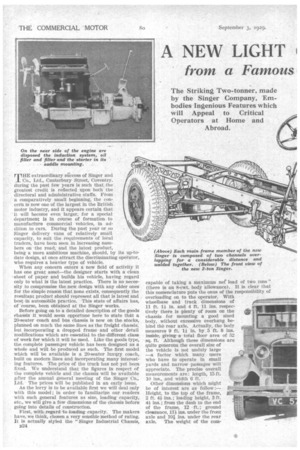
The Striking Two-tonner, made by the Singer Company, Embodies Ingenious Features which will Appeal to Critical Operators at Home and Abroad. Unusual Frame Construction which Provides Great Strength in the Centre Portion. A Floating Mounting for the Vacuum Servo-motor to Reduce its Stresses.
THE extraordinary sticcess of Singer and Co., Ltd., Canterbury Street, Coventry, during the past few years is such that the
greatest credit is reflected upon both the directoral and administrative staffs. From a comparatively small beginning, the con cern is now one of the largest in the British motor industry, and it appears certain that 'it will become even larger, for a special department is in course of formation to manufacture commercial vehicles, in ad dition to cars. During the past year or so Singer delivery vans of relatively small capacity, to suit the requirements of local traders, have been seen in increasing numbers on the road, and the latest product, being a more ambitious machine, should, by its up-todate design, at once attract the discriminating operator, who requires a heavier type of vehicle.
When any concern enters a new field of activity it has one great asset—the designer starts with a clean sheet of paper and builds his vehicle, having regard only to what is the latest practice. There is no necessity to compromise the new design with any older ones for the simple reason that none exists, consequently the resultant product should represent all that is latest and best in automobile practice. This state of affairs has, of 'course, been obtained at the Singer works.
Before going on to a detailed description of the goods chassis it would seem opportune here to state that a 20-seater coach and bus chassis is now on the stocks, planned on much the same lines as the freight chassis: but incorporating a dropped frame and other detail modifications which are essential to the different classof work for which it will be used. Like the goods type, the complete passenger vehicle has been designed as a whole and will be produced as such. The first model which will be available is a 20-seater luxury coach, built on modern lines and incorporating many interesting features. The price of the truck has not yet been fixed. We understand that the figures in respect of the complete vehicle and the chassis will be available after the annual general meeting of the Singer Co., Ltd. • The prices will be published in an early issue.
As the lorry is to be available first we will deal only with this model ; in order to 'familiarize our readers with such general features as size, loading capacity, etc., we will give a few dimensions of the chassis before going into details of construction.
First, with regard to loading capacity. The makers have, we think, chosen a very sensible method of rating. It is actually styled the "Singer Industrial Chassis, B24
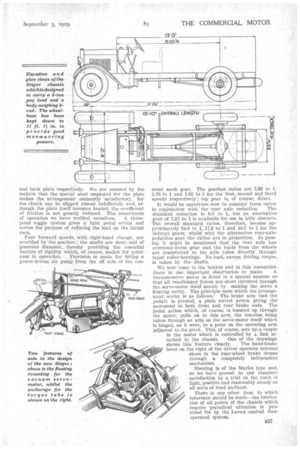
capable of taking a maximum net load of two tons,, (there is an 8-cwt. body allowance). It is clear that this nomenclature puts the onus of the responsibility of overloading on to the operator. With wheelbase and track dimensions of
11 ft. 1* in. and 4 ft. 11 ins respectively there is plenty of room on the chassis for mounting a good sized body, without excessive overhang behind the rear axle. Actually, the body measures 9 ft. 1 in. by 5 ft. 8 ins. inside, giving a total floor area of 52 sq. ft. Although these dimensions are quite generous the overall size of the vehicle is not unduly large —a factor which many users who have to operate in small yards and narrow passages will appreciate. The precise overall measurements are: length, 15 ft. 10 ins., and width 6 ft.
Other dimensions which might be of interest are as follow:
Height, to the top of the frame, r--L-1.""mmils"6"., * 2 ft. 4 ins.; loading height, 3 ft.
ins.; from the dash to the end of the frame, 12 ft. ; ground clearance, 114 ins, under the front axle and 10i ins, under the rear axle. The weight of the corn .plete vehicle when prepared fqr taxation purposes is 1 ton 194 cwt.—just within the 2-ton class.
We can now turn. to ;consideration of the struc
tural details and following our usual practice we will first -consider the general layout and then turn to the power. unit, -transmiSsion, etc. The chassis ' itself is built up on somewhat original lines, . with lightness in construction as the keynote.
Actually each side-menmer is made in two
parts, one runningfrom the front dumbiron to a position approximately in line with the forward anchorage for the, rear spring, and the other running from the rear to a position
• approximately in line with the dash, the over
lapping parts being welded together throughj out their whole length. This form of con
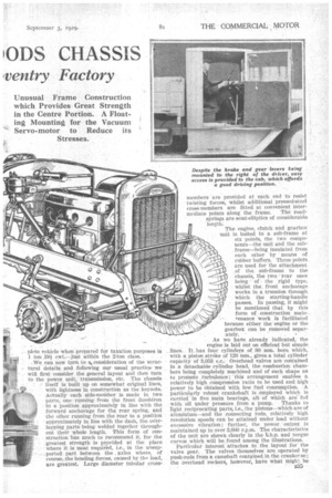
struction has much to recommend it, for the greatest strength is provided at the place where it is' most required, i.e., in the unsupported part between the . axles where, of course, .the bending forces, caused by the load, are greatest. Large diameter tubular cross members are provided at each end to resist twisting forces, whilst additional pressed-steel cross-members are fitted at convenient inter
mediate points along the frame. The roadsprings are semi-elliptics of considerable length. The engine, clutch and gearbox unit is bolted to a sub-frame at six points, the two components—the unit and the subframe—being insulated from each other by means of rubber buffers. Three points are used for the attachment of the sub-frame to the chassis, the two rear ones being of the rigid type, whilst the front anchorage works in a trunnion through which the starting-handle passes. In passing, it might be mentioned that by this form of construction maintenance work is facilitated because either the-engine or the gearbox can be removed separately.
As we have already indicated, the engine is laid out on efficient btit simple lines.. It It_ has four cylinders of 90 mm. bore which, with a piston :stroke of 120 mm., gives a total cylinder capacity of 3,053 c.c.. Overhead valves are contained in a detachable cylinder head, the combustion chambers being completely machined and of such shape as to promote .turbulence; "this arrangement enables a relatively high compression ratio to be used and high power to be Obtained with low fuel consumption. A particularly robust crankshaft is employed which is carried in five main bearings, all of which are fed with oil under pressure from a pump. Thanks to light reciprocating parts, i.e., the pistons--which are of aluminium—and the connecting rods, relatively high revolution speeds can be attained under load without excessive vibration; further, the power, output is maintained up to over 3,000 r.p.m. The characteristics of the unit are shown clearly in the b.h.p. and torque curves which will be found among the illustrations. Particular interest attaches to the layout for the valve gear. The valves themselves are operated by push-rods from a camshaft contained in the crank' se; the overhead rockers, howevei, have what migh': be termed a "geared-up" ratio for the arms. This arrangement brings down the inertia forces considerably because the valves have a larger movement than the attendant operating gear. In turn, this means that light valve springs can be used. In the Singer design the cam faces are particularly large, likewise the area of the tappets, so that the whole mechanism should run for long periods without requiring attention.
As the oiling system is of more than passing interest we will devote a little attention to a description of the various details, In the first place, it should be mentioned that there is not a solitary loose pipe in the whole engine. The pump is submerged in the oil in the sump and is driven by a vertical shaft, through the medium of skew gears, from the camshaft. Lubricant is drawn through a suction filter and delivered to a main gallery via an AutoKlean filter, the housing for which is formed integral with the crankcase. From the gallery, leads are taken to the crankshaft mainbearing journals, thence by internally drilled passages in the crankshaft itself to the big-end bearings of the connecting rods. All four bearings of the camshaft are lubricated under presB26
sure, likewise the rocker-shaft and the cup-and-ball aoints of the push-rods. This is achieved without the use of any internal' or external piping. The thoroughness with which the oiling system has been planned -will be realized when it is stated that a small quantity of oil is led through each of the• overhead rockers on to the extremities in contact with the valve stems ; the guides and valve stems, therefore, are fully lubricated all the time the engine is running.
Even in such a simple thing as the triangular form of drive from the crankshaft to the camshaft and dynamo, care has been taken to obtain the best possible results. A triple roller chain is used as the driving medium, the camshaft sprocket being rotated directly by the crankshaft sprocket with the steady ' pull of the dynamo immediately behind it ; snatch, therefore, at low speeds is reduced so far as possible. The whole layout, incidentally, is fed by oil from one of the internal ducts in the lubrication system, care being taken not to give a perfectly free outlet to the fluid which would reduce the pressure ; actually a spring-loaded piston-valve is used for regulation.
The transmission strikes something of a new note, for the forward end of the torque tube is mounted on a hinged point on the gearbox with a further joint (capable of oscillation, to take care of the criss-cross movement of the rear axle) at the junction of the torque tube proper with the gearbox hinged bracket. Rubber bushes are inserted at all the moving points and during ordinary movement of the torque tube the rubber only is distorted. This arrangement should do away with wear, obviate the necessity of lubrication and give complete freedom from transmission harshness.
The torque tube itself is strengthened up by two stays which run outwards from a point roughly midway along the tube (where there is a centre-bearing), to positions adjacent to the
spring pads. As will be realized from the illustrations, the layout for these tubes is such that structural triangulation is obtained in both vertical and horizontal planes.
Before going farther, reference should be made to the design of the clutch and gearbox. The former component has a single dry plate with a large frictional area. This plate, incidentally, operates between friction rings attached to the flywheel
. and back plate respectively. We are assured by the makers that the special steel employed for the plate makes the arrangement eminently •satisfactory, for the clutch can be slipped almost indefinitely and, although the plate itself becomes heated, the co-efficient of friction is not greatly redUced. The smoothness
of operation we have verified ourselves. A threepoint toggle system gives a light pedal action and serves the purpose of reducing the load on the thrust
race.
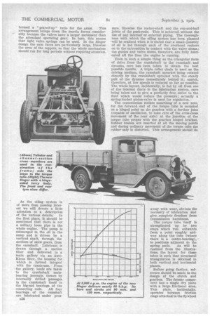
Four forward speeds, with . right-hand change, are provided by the gearbox ; the shafts are short and of generous diameter, thereby providing the essential feature of rigidity which, of „course, makes for quietness In operation.. Provision is made for fitting a power-driven air pump from the off side of the con stant mesh gear. The gearbox ratios are 5.36 to 1, 2.76 to 1 and 1.62 to 1 for the first, second and third speeds respectively;, top gear is, of course, direct. It would be opportune now to consider these ratios
in conjunction with the rear axle redudion. The standard reduction is 6.5 to I,. but an alternative gear of 7.25 to 1 is available for use in hilly districts. The overall standard ratios, therefore, become approximately 34.8 to 1, 17.9 to 1 and 10.5 to 1 for the indirect gears, whilst with the alternative rear-axlereduction -gear the ratios are in proportion. In passing it might be mentioned that the rear axle has overhead-worm gear and the loads from the wheels are transferred• to the axle tubes directly through taper roller-bearings. No load, except driving torque, is taken _ by the shafts.
We now come to the brakes and in this connection there is one important observation to make. A vacuum-servo motor is fitted in a special manner so that all reactionary forces are short circuited through the servo-motor itself merely by making the servo a floating entity. The principle upon which the arrangement works is as follows: The brake arm (not the pedal) is pivoted, a plain swivel action giving the movement to both front and, rear brake rods. The pedal action which, of course, is boosted up through the motor, pulls on to this arm, the reaction being taken through an arm on the servo-motor itself which is hinged, as it were, to a point on the operating arm adjacent to the pivot. This, of course, sets up a couple in the motor which is controlled by a link at tached to the chassis. One of the drawings shows this feature clearly. The hand-brake lever on the right of the driver operates internal shoes in the rear-wheel brake drums through a completely independent mechanism.
Steering is of the Mules type and, as we have proved to our complete satisfaction by a trial on the road, is light, positive and reasonably steady on all sorts of road surfaces.
Therre is one other item to which reference should be made—the lubrication of all points of the chassis which require periodical attention is provided for by the Luvax central footopera ted systems