


A Résumé of Recently Published Patent Specifications
Page 56
If you've noticed an error in this article please click here to report it so we can fix it.
Controlled Chassis Lubrication
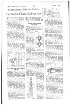
AN automatic pump for delivering a charge of lubricant at timed inter. vats is shown in patent No, 589,405, by H. Pitt and Girling, Ltd., both of Garrison Lane Birmingham, /I. The scheme is intended for chassis lubrication and other similar multi-point systems.
The chief feature is the means used to control the timed interval between charges. A piston (/) is spring-loaded to the right, in which direction it delivers a charge of lubricant from, a small pump-cyInder (2) on the end.
The piston is reset against the spring by oil supplied from the lubricating system of the engine; this arrives through a pipe and ball-valve (3). The incoming oil forces the piston to the left until' it finally meets an abutment (4) which opens escape valves (5). Oil then passes through the piston and permits the spring to perform a working stroke.
At the extrerne end the valves are closed by striking face 6. This cycle is repeated all the time that the engine is running. The frequency of operation is controlled by an adjustable leak-port (7), which starts to by-pass some of the oil, as. sonn as the piston has passed.
A MACHINE FOR BORING BRAKE DRUMS
A SPECIAL-PURPOSE machine tool ri is shown in patent No. 589,556, by H. B. Barrett Co., Ltd., St. Louis, Missouri, U.S.A. The machine is a lathe for boring the interior of brake drums while in assembly. with their associated road wheels.
The drawing indicates a hub assembly in position on the machine. The headstock, Flaying . a, self-contained motor drive, can be adjusted for height, and is set-to suit the wheel, after which final alignment is ensured by a pair of cones (1), which are tightened upon the bore of the hub. This action may lift either the wheel or the headstock from the bed, but a readjustment will correct it.
A rotary cutter-head (2) revolves around the cone spindle, normally taking a roughing cut first, followed by a finer finishing cut. The feed mechanism racks along the central spindle and gradually draws the wheeled headstock to or from the work.
A finish-grinding operation may be performed by a detachable motor 'unit, A31• which is used instead of the boring
head The whole mechanism is arranged to run -at any chosen speed within the range of the contrOr rheostats (3).
WIDE-PURPOSE RUBBER MOUNTING ARUBBER-MOUNTED unit claimed to withstand severe • stresses in all directions is shown in patent No. 589,383 by Lord Manufacturing Co., Erie, Pennsyl
vania, U.S.A.
The mounting consists of three main parts—a top unit (I), an intermediate (2), and a lower piece (3). The top and bottom units are similar and comprise a base plate, a tubular rubber member (4), and a cap plate, all of which are united by bonding. The middle member has a central ,tube, a rubber ring (5), and an outer tube, also all bonded:
The-lower drawing shows the position. ,assumed by the Mounting under vertical Iciarl, in which the upper rubber. is in
compresSion, the middle one shear, and the lower one in . tension. The
patent .gives many exartiples a different loadings and the deflection caused by .them.
STEERING SERVO MOTOR
PATENT No. 589,359, from L. Chouings and Autoinotive Products Co., Ltd., both of Tachbrook Road, Leamington Spa, deals with the application of power assistance to the steering system of a toad vehicle.
Referring to. the drawing, I is the normal steering column, at the lower end of which is the drop arm (2). The drop arm is worked by a 'double-acting piston (1), which is subjected to con
trolled hydraulic, forces. When the column is turned, its screwed end attempts to move
t h e hydraulic piston, up or down, but as the not member (4) is mounted on a ball bearing, it tends to turn With the colunin instead of moving the piston. The eontrol finger of a fluid control valve is housed in the boss (5), being operated by a keyway located in the steering nut of the device. When the nut tries to turn, it operates the valve and admits fluid to the cylinder in the, appropriate direction. The net effect is exactly as though the screwed steering column were moving the nut, but the actual force is supplied from outside.
To give the system a self-centring action,. a spring-loaded plunger (6) works in a helical keyway, so that if the steering wheel be untouched, the spring plunger will load the nut slightly until it reaches the straight-ahead position.
HEAVY-DUTY STARTER PINION
/rECHANISM intended for the start/1ft ing of the heaviettypes of engine—. compression-ignition units in particular —is shown in patent No. 589,485, by Bendix Aviation Corporation, South Bend, Indiana, U.S.A. The chief feature is the provision for accidental tooth-totooth engagement between pinion and
gear. • The mechanism works on established principles, but the drive passes through a multi-plate clutch (I), which can be adjusted to transmit a certain 'maximum torque by means of a nut (2), which varies the compressioi of the springs , (3). The quick-threaded screw is splined . into one clutcit member, but is normally held to the right by means of a set of springs (4):
Should the teeth on the pinion foul those on the flywheel ring, the 'screwed shaf.t can compress these springs andallow half a pitch of slip, after which he.pinion is snapped into mesh as soon as a tooth-pitch alignment is obtained: TREATMENT TO AID CYLINDERLINER INSERTION A SCHEME for facilitating the inserPt don of cylinder liners into their blocks is described in patent No.' 589,325 by A. Redfern and Sheepbridge Stokes Centrifugal_ Castings Co., Ltd., Sheepbridge Works, Chesterfield. The aim is to provide a "metallic lubricant" for the pressing-in operation, instead of using oil, which tends to form a break in the heat-conducting path.
The proposed treatment is to give the liner a " flash " of silver or copper plating on the outside; that is, a layer approximately 0.00005 in. in thickness. Other metals may be used, such as nickel, lead or tin.
When the liner is pressed into the block, the plating is said to act as a lubricant and give enhanced contact.