


Patents Completed.
Page 28
If you've noticed an error in this article please click here to report it so we can fix it.
OPERATING MECHANISM FOR CHUCKS.—Herbert and Another.—No. 10,588, dated 7th May, 1907.—A chuck operating tube (G) is disposed within the tubular spindle (A). At the end of this lies an intermediate piece formed in two parts (II, J). The short ends (El) of the bell crank levers (E) abut against lugs (K) formed on the intermediate piece (H). When the sliding cone (F) is moved to the left of the figure, the bell crank levers will be separated, causing the short ends to move to the right. These force the operating tube (G) to the right, and thus allow the parts to return to their normal position.
DRIVING CHAIN. — Westinghouse Brake Company and Another. — No. 16,596, dated 23rd July, 1906.—In order that the seat pin (1) of the chain may not come away when it is fractured it is provided with a shoulder (6) at each end, and these shoulders bear against the outside members of a link. The ends of the pin are riveted over washers (3), and these extend over the ends of the rocker (2). It thus follows that, though the pin may be fractured, it will not fall out and the washers will also retain the rocker in place ; this latter may be provided with a bearing surface equal to the width of the chain.
ENGINE CONTROL DEVICE.— Westmacott.—No. 18,552, dated 18th
August, 1906.—The induction pipe (e) is controlled by a lift valve (el) which is arranged within it, and this is connected to a valve rod (el), which passes through a tubular guide (c1), and through the exhaust pipe (e) ; at its lower end it rests upon a bell crank lever (d). The valve (el) is normally held upon its seat by a spring (c6). The bell crank lever (d) is pivoted at dl and is arranged to slide laterally with respect to its pivot. A roller (el) is mounted upon the arm (d) of the bell crank lever. Fixed upon the sleeve (b2), operating with the governors, is a cam (ha) which engages the roller (el) ; the cam (0), for about half of its circumference, is formed with a dwell (1.4) approached by a rise (0) which constantly acts upon the roller (d*1). By traversing the bell crank lever (d) and arm laterally, by the regulating handle (el), the position of the truck or roller (dl) with relation to the incline (b6) may be varied, and, therefore, the timing of the cut-off may be regulated within certain limits, or the throttle (cl) may be completely closed.
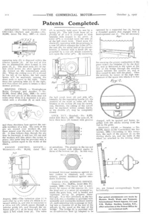
LOCK NUT.—Marshall.—No. 6,275, dated 15th March, 1907.—The nuts (A, BI have their faces (D) formed with grooves or serrations. The grooves in the top nut (A) are formed with different angles to those of the bottom nut (B). In this way, increased frictional resistance against rotary motion is obtained, and, consequently, greater resistance against automatic loosening.
LIQUID FUEL BURNING DEVICE. —Gregory.—No. 12,372A, dated 28th November, 1906.—The liquid fuel is introduced, by means of the injector (b), into the front end of a retort (a) arranged beneath the grate bars, and is heated and vaporised during its progress therethrough. It is then delivered, at the further end, into a chamber (e) provided with upwardly and rearwardly inclined nozzles (d), each extending into a passage (e) leading into a chamber (f) at the rear of the ash-pit, to the space at the rear of the bridge. The bridge (b) is provided with an air-admission door (g) adapted to be operated by a supported bar (h), having a threaded portion that engages with a hand-operated nut (i). The air necessary Zig t for ensur,ng the proper combustion of the gases enteis the chamber (f) by the door (g), and is delivered to the space at the rear of the bridge through the annular spaces between the nozzles (d), and is thus caused to mix with the gases. Then the mixture, by reason of the high temperature of the space into which it is dis
charged, will be ignited and burnt, together with the smoke arising from the fuel in the grate.
DRIVING GEAR. — Daimler. — No. 2.5,076, dated (under Convention) 8th November, 1905.—According to this invention, the teeth of the pinions (b) on the driving shafts (a), and the teeth of the wheel (a) attached to the driving wheel (m), are formed. correspondingly hyperboloidically.