


ENGINE OIL DISPLAC1 CHANGE-SPEED GEARS
Page 26
Page 27
Page 28
If you've noticed an error in this article please click here to report it so we can fix it.
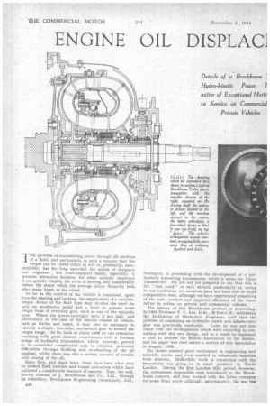
Details of a Brockhouse I Hydro-kinetic Power 7 mitter of Exceptional Me fit in Service on Commercial Private Vehicles
THE problem of transmitting power through the medium of a fluid, and particularly in such a manner that the torque can be varied either at will or, preferably, automatically, has for long exercised the minds of designers and engineers. . For road-transport media, especially, it presents attractive features, for when suitably employed it can greatly simplify the work of driving, and considerably reduce the strain which the average driver naturally feels after many hours at the wheel.
So far as the control of the vehicle is concerned, apart from the steering and braking, the employment of.a variabletorque device of the fluid type may involve the need for only an accelerator pedal and a lever to actuate some simple form of reversing gear, such as one of the epicyclic type. Where the power-to-weight ratio is not high, and particularly in the case of the heavier classes of vehicle, such as lorries and buses, it may also be necessary to embody a simple, two-ratio, mechanical gear to extend the torque range. As far back as about 1998 we can remember watching with great interest experiments with a German design of hydraulic transmission, which, however, proved to be somewhat complicated and, in addition, presented difficulties througn frothing and overheating of the oil medium, whilst there was also a certain amount of trouble with oozing of the oil.
Since then, and much later, there have been what may be termed fluid clutches and torque converters which have achieved a considerable measure of success. Now, the wellknown concern of J. Brockhouse and Co., Ltd., through its subsidiary, Brockhouse Engineering (Southport), Ltd., Southport, is proceeding with the development of a 'particularly interesting transmission, which it terms the Turbo Transmitter. We are not yet prepared to say that this is the " last word " .in such devices, particularly as, owing to war conditions, we ourselves have not been able to make comparative tests, although we have experienced something of the ease, comfort and apparent -efficiency of the transmitter in action on private and commercial vehicles.
The history of this Brockhouse product is interesting. In 1935 Professor F. C. Lea, D.Sc., M.Inst.C.E., addressing the Institution of Mechanical Engineers, said that the problem of combining an hydraulic clutch and infinite-ratio gear was practically insolvable. Later he was put into touch with the developments which were occurring in connection with this new design, and as a result he expressed a wish to address the British Association on the matter, and his paper was read before a section of this Association in August, 1938.
His claims created great excitement in engineering and scientific circles and even resulted in telephonic inquiries from America. Meanwhile, work in connection with the transmitter was going on in small premises in North London. During the first London blitz period, however, the enthusiasts responsible were introduced to the Brockhouse concern, and they worked with the latter company for some three years, although, unfortunately, the war has naturally caused considerable delay; but the Brockhouse concern has such confidence in the product that it has obtained a licence to manufacture it.
As at present designed, this combined clutch and variablespeed " gear •' gives a maximum of approximately 3.8 times engine torque with the output shaft stalled, full throttle, and an engine speed of 2,000 r.p.m. As the output shaft is released and its speed increases, the torque steadily decreases until the speed of the shaft and that of the engine coincide, when the output torque is the same as the input. i.e., that of the engine. The important point is that the torque increases while the continued resistance of the output shaft demands its rise; otherwise the ratio remains 1 to 1— in other words, the drive is direct.
Conversion from direct drive to higher torque corresponds to the use of the lower-gear ratios of a gearbox and takes place entirely automatically and instantaneously. What is more, the device selects the right ratio for the work, but, unlike what may happen when the selection is under the control of a driver, it goes into 1 to 1, i.e., top gear, whenever possible. It is, of course, impossible to obtain quite as high an efficiency as on direct drive with any " gear " ratio below top, and the efficiency decreases slightly the lower the gear required. It is for this reason that the transmitter shows its best capabilities when employed in conjunction with an engine giving a high power-weight ratio.
The progression of acceleration is so smooth as to be deceptive—in other words, it does not appear to be nearly as rapid as it really is, and it is particularly on this point that we must refrain from expressing a definite opinion until proper tests can be carried out under our own supervision.
It is realized by the company that there is still much to do in connection with the characteristics of the hydraulic circuit, for a dynamometer cannot provide all the answers. As a matter of fact, with the latest circuit the ratio has risen to 4.2 to 1 of engine torque, and this on a heavy vehicle. Naturally, an auxiliary mechanical gear provides a greater range of ratios and, consequently, higher efficiency.
One of the greatest advantages of the transmitter is its apparent freedom from wear. There are, of course, no metallic rubbing surfaces, except on the bearings, and in the free wheel which forms an essential feature of the reaction element, also all moving parts operate under ideal conditions, being constantly bathed in the light engine.oil which is used as the fluid.
Considerable mileages, without any trouble being experienced, have already been achieved. For example. one Humber car was equipped with the device in 1938 and has now run 63,000 miles without the transmitter being dismantled. This, incidentally, is claimed to give a consumption figure of 20-20.5 m.p.g., whilst acceleration tests at Brooklands are said to have resulted in achieving 0-50 m.p.h. in 10.6 secs., which was attained by holding the vehicle on the hand brake and fully depressing the accelerator, so that the highest torque was achieved to give a quick start. With an ordinary gearbox, the corresponding time was 10.4 secs., so the difference is
On another car, a Ford 30 h.p. V8, the mileage run is about 50,000, and during this usage the engine has never been touched. This car toured through France, Switzerland and Germany shortly before the war. There was ice on some of the passes, and this afforded an opportunity to give a striking demonstration. Many other cars had been forced to park, because the driving wheels could 'not obtain a grip on the icy surface, but the Ford with its Turbo Transmitter and smooth acceleration was able to climb without difficulty through wheelspin. During the whole trip the only repair effected was the replacement of a set of brake shoes. This factor of smoothness with the hydraulic transmitter undoubtedly reduces the shocks and stresses on the engine. It also presents the curious characteristic that when it is giving a higher torque the engine speed can never rise above about 2,000 r.p.m., so that it is impossible for a driver to race his engine on
the lower " gears," as can happen with a normal gearbox.
In another car run in the service of the Ministry of Supply, 40,000 miles of hard going have been achieved. After 25,000 miles the performance was tested, and it is claimed that the petrol consumption was actually better than on similar vehicles equipped with standard. gearboxes.
In the case of a lorry with a total load of 8i tons, and with a 2.15 to 1 auxiliary mechanical gear, a start was made easily on a iradient of 1 in 4. It was found with this vehicle that the petrol consumption was slightly increased.
In another lorry using a mechanical ratio of 1.7 to 1 the transmitter permitted a drawbar pull of 6,000 lb. from rest on a reasonably good surface. Its this case the test involved the rescue of a vehicle which had been bogged. and it was achieved without any " snatching." As pointed out by Professor Lea, in the past the major causes of loss of energy have been unsteadiness of motion of the liquid medium within the ducts constituting the hydraulic circuit, and shock at the inlet of the driven element. The first, although less important, is fundamental; whilst the second, although considerably graver, is a conse
quence of the former.
As the liquid has to pass from a vaned driving element to a similar driven element rotating at a greatly differing and constantly varying speed, if losses of prohibitive magnitude are to be avoided, the rotational velocity with which the liquid emerges from the driving element must be so controlled that the direction in which it impinges upon the receiving ends of the vanes of the driven element is constantly maintained without appreciable shock.
The fundamental characteristic of the Brockhouse unit is that the centrifugal pump forming the driving element is so constructed that the motion of the liquid in its ducts -remains steady for the velocities that obtain in them. Thus both the fundamental arid consequential causes of loss of energy are virtually eliminated.
Great importance of Vane Profile It has been held that to enable such a transmitter to perform effectively the functions of a clutch, the driven element must have vanes with characteristics widely different from those required for the performance of the functions of a variable gear, which would indicate the need for mechanically variable or deformable vanes. In the Broclrhouse device, however, any complication of this nature is avoided, the .profile of the vanes being such that their hydraulic action, in co-operation with that of the reaction element, varies with altering conditions, despite the fact that neither their disposition nor their conformation is variable. Reaction vanes have been evolved of such a shape that when their action is not needed, the effect of their angular disposition becomes virtually neutralized.
For ordinary purposes and lighter vehicles, the driven and reaction elements are of the single-stage type, but this construction is suitable only where the power-weight ratio is particularly favourable. Where a starting torque of a high order is required, as in a heavy lorry, the driven element and the reaction element are of the two-stage type.
As has already been mentioned, one of the main features of the transmitter is that the reaction element, being mounted on a free wheel, is at liberty to rotate idly when inoperative, i.e., when the torque ratio is I to 1 (top gear). It becomes anchored only when it is required to perform its normal function of deflecting the liquid medium during transmission at higher ratios. Incidentally, when the vehicle overruns the engine, there is no free-wheel effect, the engine being driven by the transmitter at 1 to I.
A great advantage of the design is that the vaned elements are plain die castings or stampings, the required machining involving mainly drilling and turning. Thus there are no small inserts liable to work loose.
Those of our readers who wish to obtain a full technical description of the transmitter and its hydraulic circuit should apply to the manufacturer for a reprint of Professor Lea's paper, as a complete description of the hydraulic circuit would occupy far more space than we can afford to give in these days. We may add, however, that when a supplementary gear is used with the transmitter, as is required for vehicles, tractors, etc., employed on heavy work, such a gear can be either manually or automatically controlled. It permits the transmitter to work more frequently at what we may term its upper ratios and thus avoid those periods' when, without it, the device would be working at a lower efficiency.
High Overall Efficiency Without Shock
It must, of course, be realized that the transmitter is not designed to be, and could not be made to be, 100 per cent. efficient at any particular ratio; instead, it provides an overall efficiency, both in performance and fuel economy, possibly more than comparable with those attained with a clutch and gearbox, whilst, at the same time, it eliminates shock loads.
It is obvious that the device can be employed in many other spheres. such as for railcars and locomotives using oil or petrol engines, for winches, heavy-duty engine starters, machine tools, electric vehicles, etc.