


THE CASE FOR RETARDERS
Page 35
Page 36
Page 37
If you've noticed an error in this article please click here to report it so we can fix it.
TWO CM STAFF MEN TAKE A LOOK AT PRINCIPLES AND PRACTICE
by Graham
Electrics and exhaust brakes Montgomerie
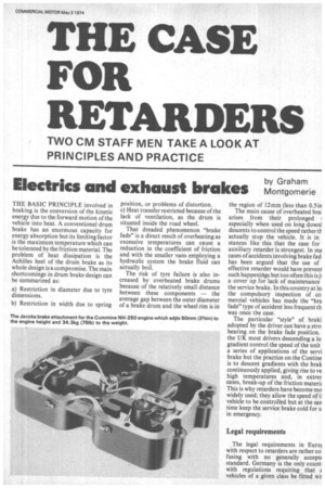
THE BASIC PRINCIPLE involved in braking is the conversion of the kinetic energy due to the forward motion of the vehicle into heat. A conventional drum brake has an enormous capacity for energy absorption but its limiting factor is the maximum temperature which can be tolerated by the friction material. The problem of heat dissipation is the Achilles heel of the drum brake as its whole design is a compromise. The main shortcomings in drum brake design can be summarized as: a) Restriction in diameter due to tyre dimensions.
b) Restriction in width due to spring position, or problems of distortion.
c) I-Teat transfer restricted because of the lack of ventilation, as the drum is situated inside the road wheel.
That dreaded phenomenon "brake fade" is a direct result of overheating as excessive temperatures can cause a reduction in the coefficient of friction and with the smaller vans employing a hydraulic system the brake fluid can actually boil.
The risk of tyre failure is also increased by overheated brake drums because of the relatively small distance between these components — the average gap between the outer diameter of a brake drum and the wheel rim is in the region of 12mm (less than 0.5 in The main cause of overheated bral arises from their prolonged I
especially when used on long down] descents to control the speed rather tlactually stop the vehicle. It is in stances like this that the case for auxiliary retarder is strongest. In ma cases of accidents involving brake fad. has been argued that the use of effective retarder would have preven1 such happenings but too often this is ji a cover up for lack of maintenance the service brake. In this country at le the compulsory inspection of co mercial vehicles has made the "bra fade" type of accident less frequent th was once the case.
The particular "style" of braki adopted by the driver can have a stro bearing on the brake fade position. the UK most drivers descending a lo gradient control the speed of the unit a series of applications of the servi brake but the practice on the Contine is to descent gradients with the brak continuously applied, giving rise to ye high temperatures and, in extrer cases, break-up of the friction mateth This is why retarders have become mo widely used; they allow the speed oft] vehicle to be controlled but at the san time keep the service brake cold for u in emergency.
Legal requirements
The legal requirements in Euroi with respect to retarders are rather co fusing with no generally accept( standard. Germany is the only count: with regulations requiring that vehicles of a given class be fitted wii .rders. All goods vehicles over 9 tons psv over 5.5 tons are required to e a retarder which will hold the fully en vehicle to 30 km/ h(18.7 mph) on a er cent gradient over a distance of n (3.7 miles). In France the reguons are rather vague in that they uire vehicles with a gvw greater than Dns to be so fitted only at the disLion of local authorities for the untainous districts.
7rance, however, does recognize the itribution to safety from the electric arder by granting a supplementary .d allowance equal to the retarder ight which can be in the region of 150 200 kg (328 to 4371b).
In the UK there is no legal requirelit and no immediate plans along se lines for the future although there ve been suggestions in the past that s situation should be altered on the minds of accident reduction.
ypes of retarder
Retarders can be generally grouped to two categories: the electrical Larder (eg Telma) and the exhaust ake which basically converts the diesel gine into a power-absorbing air cornessor (eg Jacobs).
The principle of the electric retarder is Tiple. Its operation is based on the eation of eddy currents within a metal sc rotating between the poles of two ectro-magnets. When the electroagnet is not energized the disc rotates eely but when a current is applied the rtation of the disc is retarded and the iergy absorbed is converted into heat. y varying this current the braking orque can also be varied in direct roportion.
In practice such a unit (the Telma being the most widely used) would be installed in the drive line provided sufficient space is available between the gearbox and the rear axle. The heat build-up in a retarder under operating conditions still has to be disposed of and in this respect, the unit is similar to a standard friction brake. The simple "disc" of the example quoted is in the form of a finned rotor in an actual production retarder which is made up of two discs both of which are heavily finned to provide the maximum cooling effect.
Exhaust brakes
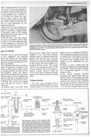
The other main principle used in increasing the braking power of a commercial vehicle is to convert the diesel engine into an air compressor which involves making use of the power required to compress the inlet charge on the compression stroke. Although covered by the general term "exhaust brake" this category can be subdivided into two sections: El Where a valve is fitted into the exhaust pipe between the manifold and the silencer. When this valve is closed, air is compressed against it on the exhaust stroke.
ID The second category involves modifying the engine rather than the exhaust system. The principle of turning the engine into a power absorbing compressor is the same but this is achieved by opening the exhaust valves near top dead centre on the compression stroke.
In the first category there are four types of valves which have been used — butterfly valves swing valves, slide valves and popper valves of which the butterfly and slide valve types are the most familiar.
The butterfly valve was incorporated in the first form of exhaust brake and is still very popular. Most modifications to its design in past years have been concerned with material refinements to reduce the erosion effects of the hot exhaust gasses passing over the valve and to prevent seizure of the spindle gland owing to carbon build-up.
This erosion effect was one of the main reasons for the interest shown in the slide valve in recent years as it overcomes the disadvantage of having the valve subject to the hot gas when in the open position by being withdrawn out of the exhaust system. This design also has a self-cleaning tendency in that any carbon adhering to the sliding portion of the valve would be sheared off during opening.
The Jacobs Brake is also an exhaust brake but not of the valve type; it is an hydraulic attachment fitted on top of the engine rocker shaft and is actuated by the engine pushrods. It works by opening the exhaust valves near the top of the normal power stroke which turns the power-producing diesel engine into a power-absorbing air compressor. The main disadvantage of the "Jake Brake" as it is usually known is that it can be fitted only to certain engines in the Cummins, Detroit Diesel and Mack range. This is because it is designed for operation on engines with injection from the main camshaft. Jacobs claims that the brake will absorb enough energy to keep a 34-tonne (33.5-ton) vehicle under complete control without the use of service brakes at 22.5 km/h (14mph) on a 10 per cent gradient.
Recently, a famous chemical company carried out some back-toback tests when two identical articulated outfits were put into service at the same time; one had the Jacobs brake fitted and the other was in standard form and both vehicles were operated on a 24-hour basis with numerous drivers at the wheel. At 69.400 km (43,000 miles) the vehicle not fitted with the Jacob' brake required relining all round and had been in the workshop 12 times for brake adjustments. The outfit fitted with the retarder eventually achieved 219,000 km (136,000 miles) before relining.
Retarder control methods
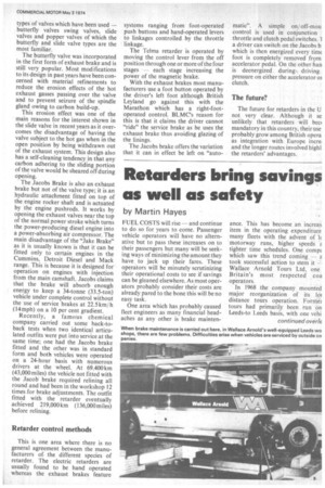
This is one area where there is no general agreement between the manufacturers of, the different species of retarder. The electric retarders are usually found to be hand operated whereas the exhaust brakes feature systems ranging from foot-operated push buttons and hand-operated levers to linkages controlled by the throttle linkage.
The Telma retarder is operated by moving the control lever from the off position through one or more of the four stages -each stage increasing the power of the magnetic brake.
With the exhaust brakes most manufacturers use a foot button operated by the driver's left foot although British Leyland go against this with the Marathon which has a right-footoperated control. BLMCs reason for this is that it claims the driver cannot "ride" the service brake as he uses the exhaust brake thus avoiding glazing of the linings.
The Jacobs brake offers the variation that it can in effect be left on "auto matic". A simple on/ off-mou control is used in conjunction throttle and clutch pedal switches. 1 a driver can switch on the Jacobs b which is then energized every timc foot is completely removed from accelerator pedal. On the other han is deenergized during k driving pressure on either the accelerator ot clutch.
The future?
The future for retarders in the U not very clear. Although it se -unlikely that retarders will bec( mandatory in this country, their use probably grow among British opera as integration with Europe incre, and the longer routes involved highl the retarders' advantages.