


Progress in Torque-converter Design
Page 58
If you've noticed an error in this article please click here to report it so we can fix it.
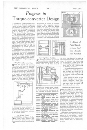
PATENT No. 425,537 shows an addition to an hydraulic torque-converter, the object of which is to provide an additional control on the liquid as it passes from the driving to the driven member, and vice versa. The inventor is W. G. Wilson, of Lower Chilland House, Martyr Worthy, Winchester.
The accompanying drawing shows the driving member (5) and the driven portion (6). The improvement consists of the interposition of two additional vaned rings (1) and (2) in the outer and inner fluid passages respectively. These rings have gear teeth, which are cut externally on ring (1) and internally on ring (2), and are interconnected by double planetary pinions (3).
The fluid acting on the vanes of ring (2) accelerates it in advance of the whole system; this movement is transmitted to the inner ring (1) by the planetary pinions, the direction of rotation being reversed. A reaction member (4) may also be used if necessary; this, however, forms the subject of a previous patent, No. 416,477.
Adding Exhaust Gas to the Fuel.
WITH the objects of increasing W economy and improving the vaporization of heavy fuel, L. V. Petersen, 76, Wakemans Hill Avenue, London, N.W.9, describes in patent No, 425,773 a device for introducing a small amount of exhaust gas into the induction pipe of an engine. Although the principle itself is not novel, the inventor claims that advantages are obtained by introducing the burnt gas at a particular point (1) in the induction pipe, that is, between the main carburetter jet (4) and the throttle valve (2). An expansion chamber (3) is used in order to smooth out the pressure variations in the exhaust system.
An All-steel Piston.
ACCORDING to L. Mousset, 97, Rue des Vignes, Liege, Belgium, castiron pistons are unduly heavy, whilst aluminium-alloy pistons are difficult to
B44 manufacture on account of expansion troubles. The suggested superior scheme, shown in patent No. 425,969 (void) is to build up a steel piston from tubes and sheet, the parts being united by welding. The drawing shows the design, in which the gudgeon-pin bosses, together with the strengthening webs, are welded to the tubular skirt. The crown is also welded in, and may, if necessary, also be supported by webs.
Improving Piston Flexibility.
AN invention intended to prevent piston-skirt distortion affecting the ring-carrying portion is shown by Wellworthy, Ltd., and J. Miles, both of
Radial Works, Stanford Road, Lyrnington, in patent No. 425,772. Referring to the accompanying drawing, the design calls for the partial isolation of the crown from the skirt by means of two circumferential slits (2) below the rings. In addition, two further slits (1) are provided in a higher plane, and cut substantially at right angles to the lower pair, so that a high degree of flexibility is obtained.
The gudgeon-pin bosses are connected by webs (4) to the crown and the lower part of the skirt, a clearance bore (3) being allowed at the point where they penetrate the skirt.
Thus, whilst the skirt is well isolated from the crown, yet adequately supported, ample provision is made for conducting heat away from the crown, via the gudgeon-pin-boss webs.
American Oil-Engine Practice.
DARTICULARS of a combustion1 chamber design are shown in patent No. 425,892 by Hercules Motors Cor
poration, Canton, Ohio, U.S.A. As will be seen from the drawing, the combustion-chamber is substantially spherical, and is connected to the cylinder space by a tangential passage of rectangular cross-section. The piston, at the top of its stroke, partly obscures this passage, the resulting restriction causing an increase in the air velocity in the chamber neck, just before the piston reaches the top of its stroke, the space being at its minimum at top dead centre.
Although no fewer than 14 claims are listed in the patent, the general design appears to be conventional. Several claims are based on the relative dimensions and angles of the chamber and nozzle, rather than on mechanical novelty.