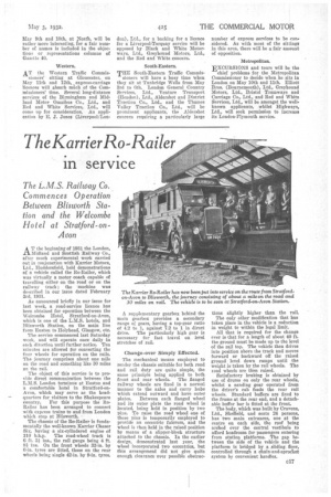
The Karrier Ro -Railer
Page 127

If you've noticed an error in this article please click here to report it so we can fix it.
in service
The L.M.S. Railway Co. Commences Operation Between Blisworth Station and the Welcombe Hotel at Stratford-on Avon
T the beginning of 1931 the London,
_Midland and Scottish Railway Co. after much experimental work carried out in conjunction with Karrier Motors, Ltd., Huddersfield, held demonstrations of a vehicle called the Ro-Railer, which was virtually a motor coach capable of travelling either on the road or on the railway track ; the machine was described in our issue dated February 3rd, 1931.
As announced briefly in our issue for last week, a road-service licence has been obtained for operation between the ‘Velcombe Hotel, Stratford-on-Avon, which is one of the L.M.S. hotels, and Blisworth Station, on the main line from Euston to Holyhead, Glasgow, etc.
The service commenced last Saturday week, and will operate once daily in each direction until further notice. Ten minutes are ellowed for converting the four wheels for operation on the rails. The journey comprises about one mile on the road and something like 30 miles on the rail.
The object of this service is to provide direct communication between the L.M.S. London terminus at Euston and a comfortable hotel •in Stratford-onAvon, which may serve as the head quarters for visitorg to the Shakespeare country. For this purpose the Ito nailer has been arranged to connect with express trains to and from London which stop at Blisworth.
The chassis of the Ro-Railer is fundamentally the well-known Karrier Chaser Six, having a six-eylindered engine of 110 b.h.p. The road-wheel track is 6 ft. 31 ins., the rail gauge being 4 ft. Si ins. On the front wheels 32-in. by 6-in. tyres are fitted, those on the rear wheels being single 42-in. by 9-in, tyres. A supplementary gearbox behind the main gearbox provides a secondary range of gears, having a top-gear ratio of 4.2 to 1, against 7.2 to 1 in direct drive. The particularly high gear is necessary for fast travel on level stretches of rail.
Change-over Simply Effected.
The mechanical means employed to render the chassis suitable for both road and rail duty are quite simple, the same principle being applied to both front and rear wheels. The flanged railway wheels are fixed in a normal manner to the axles and carry hubs which extend outward and have outer plates. Between each flanged wheel and its outer plate the road wheel is located, being held in position by two pins. To raise the road wheel one of these pins is temporarily employed to provide an eccentric fulcrum, and the wheel is then held in the raised position by means of a slipper-block structure attached to the chassis. In the earlier design, demonstrated last year, the wheel incorporated two eccentrics, but this arrangement did not give quite enough clearance over possible obstruc
tions slightly higher than, the raiL The only other modification that has taken place in the vehicle is a reduction in weight to within the legal limit.
All that is required for the change over is that for a length of about 40 ft, the ground must be made up to the level of the rail top. The vehicle then drives into position above she track and moves forward or backward off the raised, ground level down ramps until the weight is taken by the rail wheels. The toad wheels are Wen raised.
Satisfactory braking is obtained by use of drums on only the rear wheels, whilst a sanding gear operated from the driver's cab feeds the rear rail wheels. Standard buffers are fixed to the frame at the rear end, and a detachable buffer bar is fitted at the front.
The body, which was built by Cravens, Ltd., Sheffield, and seats 24 persons, has two main entrances, one at the centre on each side, the roof being arched over the central vestibule to afford headroom for passengers entering from station platforms. The gap between the side of the vehicle and the platform is bridged by. a sliding floor, controlled through a chain-and-sproclet system by convenient handles.


