


SAFETY AND EASE IN STEERING.
Page 58
If you've noticed an error in this article please click here to report it so we can fix it.
A Brief Description of the Manes V.2-type Steering Gear, which is being Used on Many Commercial Vehicles, Including Some Double-deck Six-wheeled Buses.
OF the many important components of a chassis, particularly in the case of those which are used for public-ser
vice vehicles, the steering gear may he considered as the most vital, for if it be unsatisfactory it will affect the whole performance of the vehicle and may exhaust the driver, whilst if it fails it may be the direct cause of serious accidents.
Some gears are far too stiff in operation others are too sensitive to road shocks experienced by the front wheels and transmit these to the driver, and there is nothing more racking to the nerves of the arms than to have these continually jarred in this manner.
Many gears, whilst being satisfactory at first, quickly develop backlash, necessitating constant movement of the steering wheel if the wheel is to be kept in a direct path.
The ideal type is one which will permit easy control of the vehicle, provide such a reduction that it is not an exhausting task to turn the front wheels to a large lock, and in itself provide a resistance against the reaction from the front wheels, In this connection one of the most successful steering gears on the market is the Marks V.2 type, made by the Adamant Engineering Co., Ltd. DaBow Road, Luton, which is now being supplied to a number of makers of commercial motor vehicles and is fitted to some of the largest double-deck, rigidframe six-wheeled buses.
The gear operates on a fully patented principle, very different from that employed on other types. It has no pinions, and what would in the ordinary way be the worm on the steering shaft is replaced by a hardened-steel cam, in which is cut a spiral groove. At the inner end of the spindle carrying the drop arm is a stout fork, formed in tegrally with it. This fork projects towards the cam and carries a stout spindle, upon which is mounted two ball-race cups, carrying between them, by means of large steel balls, a hardened steel roller, the periphery of which is of a foreshortened wedge shape formed to the same angle as the spiral groove in the cam.
The cam itself is mounted between two long phosphor-bronze bearings, which ensure freedom from excessive wear. At the upper end of the shaft carrying this cam, at a point just below the steering wheel, is a third bearing, which forms a steady and prevents the entry of dust. The rocker shaft also is carried in long, phosphor-bronze bearings.
The Merles gear is really extraordic36 narily simple. As the steering wheel and, consequently, the cam are rotated, the roller is forced to follow the path of the groove in the cam ; at the same time it revolves around its own axis, owing to the pressure between it and the sides of the groove in the cam. Thus there is practically no sliding friction between the surfaces of the cam and roller. This is one of the chief reasons for the smooth action of the gear and the ease with which it can be operated.
Both the contacting surfaces are of hardened steel, and practical tests have shown that, even after years of service, backlash has not appeared.
As a result of this absence of wear it is claimed that no adjustments of the moving parts are necessary ; but, actu ally, mean., for adjustment are provided. These are, however, mainly intended to be used in ease of accident or damage.
In gears of the ordinary type wear never takes place evenly, and this is one of the chief reasons for the tendency to jam when the wheels are given a bigger lock than usual. Practically all the wear is confined to the centre of the sector and of the worm, and in case of adjustment being made to take up this wear the remaining unworn teeth and that portion of the worm not normally employed are apt to bind.
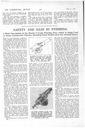
The means for adjustment to which we have referred are two in number. They control the engagement between the roller and earn and the position of the bushes between which the cam revolves. In the first case the ball-races upon which the roller is carried are mounted on a pin which has two diameters at its ends, these being concentric with each other and fitted snugly in the horns or fork of ihe rocker shaft; the middle part of the pin, however, is slightly eccentric and, consequently, the roller with its races can be raised en lowered by rotating this pin, which, after adjustment, can be locked in any desired position by means of its two nuts and locking washess.
After carrying out an adjustment it is important, first, to lock the nut at that end of the pin opposite to the end in which is the slot for a screwdriver.
To raise the roller relatively to the centre-line of the rocking shaft, thereby giving deeper engagement with the cam, the eccentric pin must be turned in a clockwise direction when looking at the slotted end.
When this adjustment is correctly made it will be found that there is a slight amount of backlash at the two ends of the cam movement, but absolutely none in the centre of the straightahead position.
The roller must, of course, not be advanced sis far as to stiffen the movement,
With the second adjustment there is between the box casting and column support a thin washer. This is of a special type, made up of a number of laminations, which may be separated. End-play on the cam between its thrust faces may, therefore, be taken up by removing one or more of these laminations and thus allowing the thrust face carried by the column support to enter farther into the steering box. The adjustments should be so made that, after the coleme support is again bolted securely to the box casting, the cam and steering-wheel shaft should revolve freely, but there should be no end-play.