


Synchromesh Gears for Heavy Vehicles
Page 60
If you've noticed an error in this article please click here to report it so we can fix it.
THE invention shown in patent No. 632,861, which relates to synchromesh mechanisms, particularly as applied to the gearbox of a large vehicle, comes from E. M'Ewen, 29, Montpelier Row, Twickenham. In the scheme proposed, the synchronizing clutches are made as separate units and are spaced apart from the main shafts.
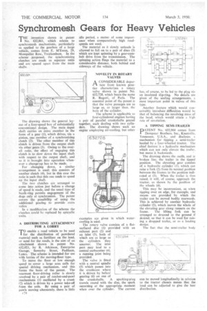
The drawing shows the general layout of a four-speed box of substantially conventional design. The main input shaft carries an extra member in the form of a gear (1), which drives, via a pinion, one member of a synchronizing clutch (2). The other member of this clutch is driven from the output shaft via other gears (3). Owing to the overall ratio, the effect of engaging this clutch is to slow down the input shaft with respect to the output shaft, and so it is brought into operation whenever a change-up has to be made, For changing down, a similar arrangement is used; this consists of another clutch (4), but in this case the ratio is such that this one tends to speed up the input shaft.
The two clutches are arranged to come into action just before a change of speed is made, and the usual type of baulk-ring permits engagement of the dogs only at synchronism. The patent covers the possibility of using the additional gearing to provide extra ratios.
In a modification of the scheme the clutches could be replaced by epicyclic units.
A DISTRIBUTING ATTACHMENT FOR A LORRY
TO enable a road vehicle to be used for the distribution of powdered material such as fertilizer on the land, or sand for the roads, is the aim of an attachment shown in patent No. 632,021, by R. Atkinson, Enterprise Garage, Sowerby Street, Padiham, Lancs. The scheme is intended for use with lorries of the moving-floor type.
To move the floor at low enough speed to cover a large area calls for special driving mechanism, and this forms the basis of the patent. The rearmost floor-driving roller is slowly revolved by a pair of ratchet-and-pawl mechanisms (1) oscillated by a crank 12) which is driven by a power take-off from the axle. By using a pair of pawls moving alternately, there is little
r24 idle period, a matter of some importance when comparatively high roadspeeds are used.
The material as it slowly unloads is allowed to fall on to a pair of discs (3) which are kept spinning by a gear-cumbelt drive from the transmission. The spinning action flings the material to a considerable distance, both behind and sideways of the vehicle.
NOVELTY IN ROTARY VALVES
A CONSIDERABLE depart-A ture from known practice characterizes a rotary valve shown in patent No. 632.728, which bears the name R. Bugatti, of Paris. The essential point of the patent is that the valve passages are as large as, or larger than, the bore of the cylinder.
The scheme is applicable to four-cylindered engines having a pair of parallel crankshafts geared together, each dealing with two cylinders. The drawing shows such an ermine employing air-cooling, but other examples are given in which watercooling is used.
The rotary valve consists of a flatsurfaced disc (1) provided with an exhaust port (2) and an inlet (3), both of which are as large as the cylinders they uncover. The inlet port may lead to a central carburetter (4), a running joint being provided.
The valve is fitted with a central spindle (5) which passes into the crankcase where it is driven by helical gearing (6) on one of the crankshafts. A sparking-plug travels round with the disc, the spark occurring at the appropriate moment when over the cylinder. The current
has, of course, to be led to the plug via an insulated slip-ring. No details are given of the sealing arrangements, a most important point in valves of this type.
Another feature which would conceivably introduce difficulties would be that of balancing the revolving mass of the head, which would attain a high rate of revolution.
A TIPPING SEMI-TRAILER
PATENT No. 632,964 comes from Dempster Brothers, inc., Knoxville, Tennessee, U.S.A., and discloses a mechanism for tipping a semi-trailer hauled by a four-wheeled tractor. The chief feature is a hydraulic mechanism which can not only elevate the trailer, but move it backwards.
The drawing shows the outfit, and in broken line, the trailer in the tipped position. The elevating gear consists of a hydraulic cylinder (1), which can raise a fork (2) from its normal position between the frames to the position indicated at (3). When the trailer is thus raised, it will, of course, approach the tractor, as shown by the position of the wheels (4).
This may be inconvenient, as when tipping over an edge, for example, and means are provided by which the trailer can be moved bodily rearwards. This is achieved by another hydraulic cylinder (5), which moves the whole of the elevating gear along runners on the frame. The lifting fork can be arranged to descend to the ground if desired, so that it can be used for raising a dropped trailer, or as a loading device.
The fact that the Semi-trailer body
can be moved longitudinally in relation to the tractor chassis means that the load can be adjusted to give the best distribution.