


BRITAIN'S MOST POWERFUL VEHICLE
Page 48
Page 49
Page 50
Page 51
Page 52
Page 55
If you've noticed an error in this article please click here to report it so we can fix it.
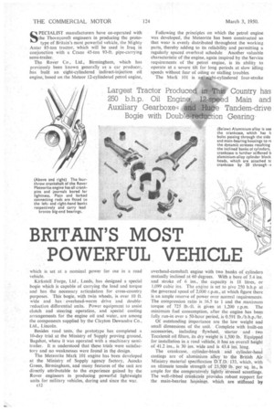
Largest Tractor Produced in This Country has 250 b.h.p. Oil Engine, 12-speed Main and Auxiliary Gearboxe,4 and Huge Tandem-drive Bogie with Double-reduction Gearing S-11 PECIALIST manufacturers have co-operated with the Thor nycroft engineers in producing the prototype of Britain's most powerful vehicle, the Mighty Antar 85-ton tractor, which will be used in Iraq in conjunction with a Crane 45-ton 93-ft. pipe-carrying semi-trailer.
The Rover Co., Ltd., Birmingham, which has previously been known generally as a car producer, has built an cight-cylindered indirect-injection oil engine, based on the Meteor 12-cylindered petrol engine, which is set at a nominal power for use in a road vehicle.
Kirkstall Forge, Ltd, Leeds, has designed a special bogie which is capable of carrying the load and torque and has the necessary articulation for cross-country purposes. This bogie, with twin wheels, is over 10 ft. wide and has overhead-worm drive -and doublereduction differential units. Power equipment to assist clutch and steering operation, and special cooling arrangements for the engine oil and water, are among the components supplied by the Clayton Dewandre Co., Ltd., Lincoln.
Besides road tests, the prototype has completed a 10-day trial at the Ministry of Supply proving ground, Bagshot, where it was operated with a machinery semitrailer. It ts understood that these trials were satisfactory and no weaknesses were found in the design.
The Meteorite Mark 101 engine has been developed at the Ministry of Supply agency factory, Aeocks Green, Birmingham, and many features of the unit are directly attributable to the experience gained by the Rover engineers in producing powerful lightweight units for military vehicles, during and since the war.
c12 Following the principles on which the petrol engine was developed, the Meteorite has been constructed so that wear is evenly distributed throughout the working parts, thereby adding to its reliability and permitting a regularly spaced overhaul schedule Another valuable characteristic of the engine, again inspired by the Service requirements of the petrol engine, is its ability to operate at a severe tilt for long periods at slow idling speeds without fear of oiling or stalling troubles. The Mark 101 is an eight-cylindered four-stroke
overhead-camshaft engine with -two banks of cylinders mutually inclined at 60 degrees. With a bore of 5.4 ins. and stroke of 6 ins., the capacity is 18 litres, or 1,099 cubic ins. The engine is set to give 250 b.h.p at the governed speed of 2,000 r.p.m., at which figure there is an ample reserve of power over normal requirements The compression ratio is .16.5 to 1 and the maximum
torque of 725 lb.-ft. is given at 1,200 r.p.m. The minimum fuel consumption, after the engine has been fully run-in over a 50-hour period, is 0.591 lb./b.h.p./hr. Of outstanding importance are the low weight and small dimensions of the unit. Complete with built-on accessories, including flywheel, starter and two Tecalemit oil filters, its dry weight is 1,500 lb. Equipped for installation in a road vehicle; it has an overall height of 41.2 ins., is 30 ins, wide and is 43.4 ins. long. . . . The crankcase,, cylinder-block and cylinder-head
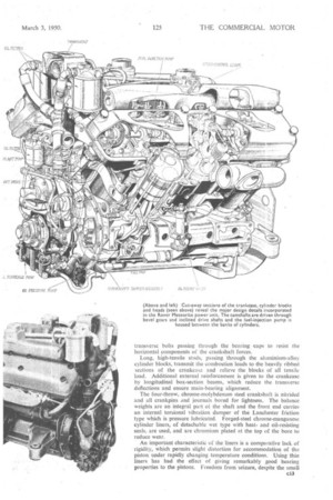
castings are of aluminium alloy.'to: the British Air Ministry material Specification D.T.13.-433, which, with an ultimate tensile strength Of 23;540 lb.; per sq in., is ample for the comparatively lightly stressed scantlings. The well-ribbed etinkaale provides robust support for the main-bearina hOsirigs, which are stiffened by
transverse bolts passing through the bearing caps to resist the horizontal components of the crankshaft forces.
Long, high-tensile studs, passing through the aluminium-alloy. cylinder blocks, transmit the combustion loads to the heavily ribbed sections of the crankcase and relieve the .blocks of all tensile load. Additional external reinforcement is given to the crankcase by longitudinal box-section beams, which reduce the transverse deflections and ensure main-bearing alignment.
The four-throw, chrome-molybdenum steel crankshaft is nitrided and all crankpins and journals bored for lightness. The balance weights are an integral part of the shaft and the front end carries an internal torsional vibration damper of the Lanchester friction type which is pressure lubricated. Forged-steel chrome-manganese cylinder liners, of detachable wet type with heatand oil-resisting seals, are used, and are chromium plated at the top of the bore to reduce wear.
An important characteristic of the liners is a comparative lack of rigidity, which permits slight distortion for accommodation of the piston under rapidly changing temperature conditions. Using thin liners has had the effect of giving remarkably .good bearing properties to the pistons. Freedom from seizure, despite the small
piston clearances, is another proven characteristic of the thin liners.
A controlled flow of cooling water is a feature of the cylinder head which incorporates a central baffle to nullify the effects of differential expansion. There are slots between each cylinder in the main combustionchamber deck. A new pressure-balanced "thermostat has been developed for the engine to provide a stable temperature control unaffected by pressure differences in the cooling system.
A detachable pre-combustion chamber of the Ricardo Comet Mark III design is used, the upper half carrying the injector, whilst the lower half serves as the hot plug. Research by the Rover company, backed by experience in the development of gas-turbine bIading, led to the production of a high-chromium steel for the chamber, which is completely adequate to resist the localized high temperatures associated with this type of head. The original throat angle has also been changed to obviate overheating of the piston in the vicinity of the throat and the rapid formation of carbon around the piston rings.
The camshafts are single-piece forgings supported in five white-metal bearings and one phosphor-bronze bearing, the latter taking the load of the bevel-drive gears. The two rocker fulcrum shafts, one each side of the camshaft, are carried by the pedestal-type bearing housings.
Two inlet valves, each of ins, nominal diameter, and one sodium-cooled exhaust valve of 2 ins, nominal diameter, are employed, the exhaust valve being Stellite tipped and seated with Brightray. Silehrome inlet-valve seats are used and all valve seats are screwed and shrunk into the heads. The twin valve springs fitted to each valve are treated as a protection against corrosion.
Pistons of low-expansion silicon alloy are fitted, each carrying three compression rings and three oil-control rinp. An anodized surface finish is applied for its corrosion-resistant and oil-retaining properties. The pistons are ribbed internally and the gudgeon pin is placed at the lower section of the skirt for cool funning.
Plain and forked connecting rods, with a separate big-end bearing block, are used for opposite rod assemblies. The big-end bearings are of lead bronze and plated with a tin flash as a provision against local overheating during running-in and the early service life of the engine.
A low-pressure oil circuit, designed •to provide a uniform supply of oil to the valve gear, irrespective of bearing wear, is an interesting feature of the dry-sump lubrication system. Two compounded relief valves give a boosted pressure to the low-pressure system when the oil viscosity, is high, thus preventing starvation when starting from cold, but pressure is kept constant when nonnal temperature conditions have been established. A large-capacity relief valve in the pressure-pump system gives protection against excessive loading of pump gears and drives under very cold conditions. A normal pressure-relief valve controls the full-flow oil pressure to the main bearings and other working parts in the system. Oil is supplied to the fully floating gudgeon pins by splash. The duplex-type scavenge pump has one suction intake at each end of the sump.
C.A.V. fuel pump and pintle-type injector equipment is used, the governor being of the conventional pneumatic type connected to an induction-manifold venturi.
A torsion-spring shaft, fitted with a damper, takes the drive from the front of the crankshaft to the auxiliary gears and reduces the angular velocity variations, caused by uneven torque of the camshafts, in the drives to the oil and water pumps. Situated above the timing case, the centrifugal coolant pump is driven from bevel gears through a vertical shaft fitted with a seal and a " tin-hat " thrower, which prevents any leakage of water from entering the case. Lower bevel gears transmit the drive to the oil pumps. The centrally mounted fuel pump is driven by a gear train at the rear of the engine.
A feature of the flywheel attachment is the use of tubular dowels, which transmit the drive and relieve the bolts from shear loading. The rear of the crankcase, which forms the gear housing, may be fitted with one of two types of gearbox and provides a horizontal or an inclined drive for special accessories.
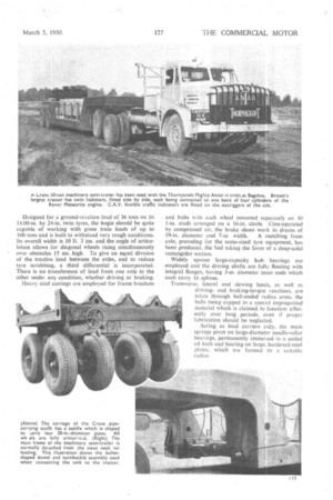
Each cylinder block is cooled by a forward-mounted radiator, the fans being driven by pulleys on a shaft from the wheel case, which is co-axial with the crankshaft. Twin oil-bath air filters are fitted. The engine is mounted on a sub-frame bolted to the crankcase, The new Kirkstall giant bogie, which is incorporated in the Thornycroft Mighty Antar, has been a subject of research for a long time, since it was realized by the manufacturer that a world demand was being developed for outsize machines to be used in oilfields and in similar terrain Long and rigorous testing was undertaken and the unit is reported to be quiet and efficient in action, with the expectation of lengthy, trouble-free service. Designed for a ground-reaction load of 36 tons on its 14.00-in. by 24-in, twin tyres, the bogie should be quite capable of working with gross train loads of up to LOU tons and is built to withstand very rough condiuons. Its overall width is 10 ft. 3 ins, and the angle of articulation allows for diagonal wheels rising simultaneously over obstacles 15 ins. high. To give an equal division of the tractive load between the axles, and to reduce tyre scrubbing, a third differential is incorporated. There is no transference of load from one axle to the other uncle' any condition, whether driving or braking.
Heavy steel castings are employed for frame brackets and hubs with each wheel mounted separately on 10 I-in, studs arranged On a 16-in. circle. Cam-operated by compressed air, the brake shoes work in drums of 19-in, diameter and 7-in. width. A matching front axle, providing for the same-sized tyre equipment, has been produced, the bed taking the form of a deep-solid rectangular section.
Widely spacea large-capacity hub bearings are employed and the driving shafts are fully floating with integral flanges, having 3-in, diameter inner ends which each carry 16 splines.
Transverse, lateral and slewing loads, as well as drivingand braking-torque reactions, are taken through ball-ended radius arms, the balls being cupped in a special impregnated material which is claimed to function efficiently over, long periods, even if proper lubrication should be neglected.
Acting as load carriers only, the main springs pivot on large-diameter needle-roller bearings, permanently immersed in a sealed oil bath and bearing on large. hardened-steel plates, which are formed to a suitable radius The rearmost axle could, if required, be employed tione in the construction of a four-wheeled tractor or dumper of 27 tons gross weight.
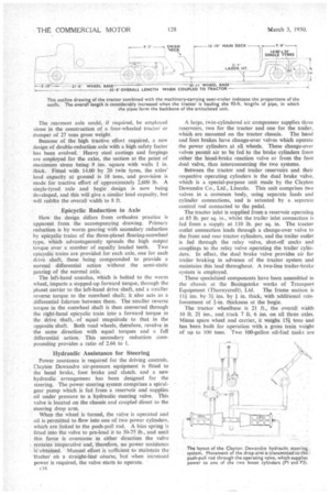
Because of the high tractive effort required, a new design of double-reduction axle with a high safety factor has been evolved. Heavy steel castings and forgings arc employed for the axles, the section at the point of maximum stress being 9 ins, square with walls I in. thick. Fitted with 14.00 by 20 twin tyres, the axles' load capacity at ground is 18 tons, and provision is made for tractive effort of approximately 2,600 lb. A single-tyred axle and bogie design is now being developed, and this will give a similar load capacity, but will reditee the overall width to 8 ft.
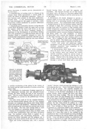
Epicyclic Reduction in Axle How the design differs from orthodox practice is apparent from the accompanying drawing. Primary reduction is by worm gearing with secondary reduction by epicyclic trains of the three-planet floating-sunwheel type, which advantageously spreads the high output torque over a number of equally loaded teeth. Two epicyclic trains are provided for each axle, one for each drive shaft, these being compounded to provide a normal differential action without the semi-static gearing of the normal axle.
The left-hand annulus, which is bolted to the worm wheel, imparts a stepped-up forward torque, through the planet carrier to the left-hand drive shaft, and a smaller reverse torque to the sunwheel shaft; it also acts as a differential fulcrum between them. The smaller reverse torque in the sunwheel shaft is then converted through the right-hand epicyclic train into a forward torque in the . drive shaft, of equal magnitude to that in the opposite shaft. Both road wheels, therefore, revolve in the same direction with equal torques and a full differential action. This secondary reduction compounding provides a ratio of 2.66 to I.
Hydraulic Assistance for Steering Power assistance is required for the driving controls. Clayton Dewandre air-pressure equipment is fitted to the hand brake, foot brake and clutch, and a new hydraulic arrangement has been designed for the steering. The power steering system comprises a spiralgear pump which is fed from a reservoir and supplies oil under pressure to a hydraulic steering valve. This valve is located on the chassis and coupled direct to the steering drop arm.
When the wheel is turned, the valve is operated and oil is permitted to flow into one of two power cylinders. which are linked to the push-pull rod. A bias spring is fitted into the valve to pre-load it to 50-75 lb., and until this force is overcome in either direction the valve remains inoperative and, therefore, no power assistance is obtained Manual effort is sufficient to maintain the tradtor on a straight-line course, but when increased power is required, the valve starts to operate.
cl 6
A large, twin-cylindered air compressor supplies three reservoirs, two for the tractor and one for the trailer, which are mounted on the tractor chassis. The hand and foot brakes have change-over valves which operate the power cylinders at all wheels. These change-over valves permit air to be fed to the brake cylinders from either the hand-brake reaction valve or from the foot dual valve, thus interconnecting the two systems.
Between the tractor and trailer reservoirs and their respective operating cylinders is the dual brake valve, which is a special-purpose unit made by the Clayton Dewandre Co., Ltd., Lincoln. This unit comprises two valves in a common body, using separate feeds and cylinder connections, and is actuated by a separate control rod connected to the pedal.
The tractor inlet is supplied from a reservoir operating at 85 lb. per sq. in., whilst the trailer inlet connection is fed from a supply at 110 lb. per sq. in. The tractor outlet connection leads through a change-over valve to the front and rear tractor cylinders, and the trailer outlet is fed through the relay valve, shut-off cocks and couplings to the relay valve operating the trailer cylinders. In effect, the dual brake valve provides air for trailer braking in advance of the tractor system and maintains this lead throughout. A two-line trailer-brake system is employed.
These specialized components have been assembled in the chassis at the Basingstoke works of Transport Equipment (Thornycroft), Ltd. The frame section is 114 ins. by 31 ins, by in. thick, with additional reinforcement of It-in, thickness at the bogie.
The tractor wheelbase is 21 ft., the overall width 10 ft. 21 ins., and track 7 ft. 6 ins, on all three axles. Minus spare wheel and carrier, it weighs 151 tons and has been built for operation with a gross train weight of up to 100 tons. Two 100-gallon oil-fuel tanks are
fitted and the supply to the engine is by duplex pumps.
Main and auxiliary gearboxes, with four and three speeds respectively, afford a selection of 12 forward ratios Constant-mesh gearing is provided for all ratios, the maximum speed in overdrive being 28 m.p.h. The clutch is an 18-in.-diameter two-plate assembly with power assistance for its operation Outsize semi-elliptic springs are fitted, those at the front being 48 ins long and 4 ins, wide, whilst the single springs at the bogie are 62 ins, long and 5 ins. wide. Single tyres are fitted to the front wheels and twins on the bogie, the standard equipment for tractor and semitrailer being 14.00 by 24 ins., 20 ply.
The 24-volt batteries, starting, lighting and other electrical equipment are of C.A.V. manufacture, Nife batteries of 320 amp.-hour capacity being supplied to the order of the Iraq Petroleum Co. Two starter motors are employed, and the engine has a flame heater for extremely cold starting.
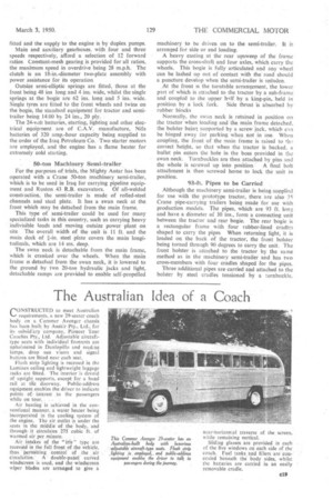
50-ton Machinery Semi-trailer For the purposes of trials, the Mighty Antar has been operated with a Crane 50-ton machinery semi-trailer, which is to be used in Iraq for carrying pipeline equipment and Ruston .43 R.B. excavators. Of all-welded consn uction, the semi-trailer is made of rolled-steel channels and steel plate. It has a swan neck at the front which may be detached from the main frame_ This type of semi-trailer could be used for many specialized tasks in this country, such as carrying heavy indivisible loads and moving outsize power plant on site The overall width of the unit is. 11 ft. and the main deck of t-in. steel plate covers the main longitudinals, which are 14 ins. deep.
The swan neck is detachable from the main frame, which is cranked over the wheels. When the main frame is detached from the swan neck, it is lowered to the ground by two 20-ton hydraulic jacks and light, detachable ramps are provided to enable self-propelled
machinery to be driven on to the semi-trailer. It is arranged for side or end loading. .
A heavy casting at the rear upsweep of the frame supports the cross-shaft and four axles, which carry the wheels. This bogie is fully articulated and any wheel can be lashed up out of contact with the road should a puncture develop when the semi-trailer is unladen.
At the front is the turntable arrangement, the lower part of which is attached to the tractor by a sub-frame and coupled to the upper half by a king-pin, held in position by a lock fork, Side thrust is absorbed by rubber blocks
Normally, the swan neck is retained in position on the tractor when loading and the main .frame detached, the bolster being supported by a screw jack, which ean be hinged away for parking when not in use. When coupling, the front of the main frame is raised to th-; correct height, so that when the tractor is backed, a bullet pin enters the hole in the boss provided in the swan neck. Turnbuckles are then attached by pins and
the whole is screwed up into position. A final bolt attachment is then screwed home to lock the unit in position.
93-ft. Pipes to be Carried
Although the machinery semi-trailer is being supplied for use with the prototype tractor, there are also 35 Crane pipe-carrying trailers being made for use with production models. The pipes, which are 93 ft. long and have a diameter of 30 ins., form a Connecting unit between the tractor and rear bogie. The rear bogie is a rectangular frame with four rubber-lined cradles shaped to carry the pipes When returning light, it is loaded on the back of the tractor, the front bolster being turned through 90 degrees to carry the unit. The front bolster is attached to the tractor by the same method as in the machinery semi-trailer and has two cross-members with four cradles shaped for the pipes.
Three additional pipes are carried and attached to the bolster by steel cradles tensioned by a turnbuckle.