A Quickly Detachable Tow-bar
Page 36

If you've noticed an error in this article please click here to report it so we can fix it.
A N emergency towbar, for enabling one vehicle to haul another, is shown in patent No. 558,238, by A. Goodliffe and the London Passenger Transport Board, 55,
Broadway, Lon don, S.W.1. The aim of the design is to enable the act of coupling to be quickly and easily performed, with the minimum of man ho ndling.
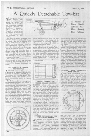
The drawing shows a broken view, actually, the two ends (1 and 5) should be united. The bar is mounted on a pair of road wheels to enable it to be quickly run into position. The rear end is fitted with a pair of pincer-like jaws (2), Which grip the front axle (3) of the disabled vehicle. A screwoperated lazy-tongs closes the jaws, to actuate which the operator turns a handwheel (6). A pivot pin 14) permits cornering and a lighting systern (not shown) is provided to facilitate working in the dark.
The frame and wheels are made strong enough to carry the front-axle weight of the disabled vehicle, if the extent of the damage necessitates this course.
AN HYDRAULIC POWER ,. TRANSMITTER A DEVICE which is claimed to tuner/ thin a.S. an infinitely variable gear is shown in patent No. 558,227, by P. leVoodhams, 12, Thornhill Road, West Crojrdon, Surrey: It is intended for use in the transmission system of a Motor vehicle.
The device consists of a casing forniing four radial cylinders, the pistons of which are attached to a common crankpin formed on the central shaft. The casing. and cylinders are revolved by the 'engine, whilst the central shaft forms the output member: The interior of the casing is filled with oil; this, as it is pumped out by One piston, is received by its opposite'number, so that the pistons idly reciprocate and no power is _transmitted, but a ported ring (1) can be moved . circumferentially so as• to obstruct the cylinder heads, and when this is done, the whole assembly becomes hydraulically locked and a straight-through drive can then be transmitted. The closing of the cylinders may he controlled automatically, as by bob-weights (2) which are responsive to engine speed.
Although the device would give a gentle take-up from •a standing start, we can see no reasonwhy it should act as a gearbox. When the valve is in a partly obstructing position, the energy not being transmitted would appear in the form of heat generated by the squirting-out of the • oil through the
nearly closed valve. This is a phenomenon known to steam engineers as '' Wire-drawing."
EASING ASSEMBLY OF' NEEDLE-ROLLER BEARINGS
NEEDLE rollers, owing to their small eize. May be troublesome to assemble, and to ease this difficultyis • the object of a retaining ring shown in patent No. 558342, •by Hardy Spicer and Co.,. Ltd‘, and T. Green; both of Birch Road, Birmingham, 6. The basis of the scheme is a means for attaching the ring of the rollers to the outer race, which can then he handled and assembled as an integral unit.
In the drawing, 4 show the outer race and 3 the rollers. The latter have pointed ends, and these are imprisoned in . an annular groove formed in a pressed-steel ring (1) Two of these rings are forced on to the outer race and snap into undercuts' (2) which effectively maintain assembly, even when the race is being driven into its 'housing.
POWDER METALLURGY FOR VALVE-SEAT INSERTS
./"/ A N inserted valve seat has to with stand severe conditions in use, being subjected to heavy impacts under high-temperature conditions ; moreover, the initial pressing-in operation may also impose severe stresses. An improved method of 'manufacture, which is claimed to pro
duce a seating capable of withstanding this treatment, is shown in patentNo. 558,182, by the British Piston Ring Co., Ltd., Holbrook Lane, Coventry, and others.
Powder metallurgy is the basis of the process, the constituents being mixed
a finely divided state and, subsequently, solidified by a sintering process. Several mixtures are' proposed, the following being typical :Iron, plus 1;1 to 4 per cent, carbon, 1 to 10. per cent. chromium, and molybdenum 11 per cent. to 10 per Cent, with -the usual amounts Of phosphorus and sulphur: If an austenitic..structure be required, the• iron may contain nickel, copper, manganese,. molybdenum, and silicon. . Non-metals, such as graphite, may be added to facilitate the pressing operation: 'FLEXIBLE JOINT EMPLOYING . , WIRE CABLES A FLEXIBLE transmission joint;,in stranded wire cables are used kir. the resilient member, forms the ..gtilf;jeOt of patent No. 558,242, front T. Hirst, 163, WoOdside. Avenue, Coventry, The particulars given illustrate only the basic principle, few constructional details being mentioned. The -driving and driven members (1 and 3) are located in the same plane, and the inner one is spherically mounted in the outer, so that it can move universally. The driving connection is ,a set of wire cables (2), which, chordal-wise,' intersect both members and transmit the torque while permitting angular deflectioneAlthough no Mention is madeof it, the bores around the wires mutt 'be'given ample clearance to save the rabies from damage by. shearing.


