 1
1 2
2 3
3 4
4 5
5 6
6 7
7 8
8 9
9 10
10 11
11 12
12 13
13 14
14 15
15 16
16 17
17 18
18 19
19 20
20 21
21 22
22 23
23 24
24 25
25 26
26 27
27 28
28 29
29 30
30 31
31 32
32 33
33 34
34 35
35 36
36 37
37 38
38 39
39 40
40 41
41 42
42 43
43 44
44 45
45 46
46 47
47 48
48 49
49 50
50 51
51 52
52 53
53 54
54 55
55 56
56 57
57 58
58 59
59 60
60 61
61 62
62 63
63 64
64 65
65 66
66 67
67 68
68 69
69 70
70 71
71 72
72 73
73 74
74 75
75 76
76 77
77 78
78 79
79 80
80 81
81 82
82 83
83 84
84 85
85 86
86 87
87 88
88 89
89 90
90 91
91 92
92 93
93 94
94 95
95 96
96 97
97 98
98 99
99 100
100 101
101 102
102 103
103 104
104 105
105 106
106 107
107 108
108 109
109 110
110 111
111 112
112 113
113 114
114 115
115 116
116 117
117 118
118 119
119 120
120 121
121 122
122 123
123 124
124 125
125 126
126 127
127 128
128 129
129 130
130 131
131 132
132 133
133 134
134 135
135 136
136 137
137 138
138 139
139 140
140 141
141 142
142 143
143 144
144 145
145 146
146 147
147 148
148 149
149 150
150 151
151 152
152 153
153 154
154 155
155 156
156 157
157 158
158 159
159 160
160 161
161 162
162 163
163 164
164 165
165 166
166 167
167 168
168 Dennis/Metz Turntable kppliance
Page 94
Page 95
Page 96
Page 101
If you've noticed an error in this article please click here to report it so we can fix it.
By R. D. Cater,
AM Inst BE
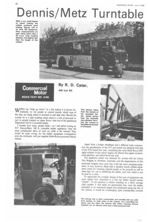
WHEN the "bells go down" in a fire station it is known immediately by the people in control exactly which type of fire they are being asked to proceed to and deal with. Should the trouble be in a high building where there is a risk of personal injury to people trapped on upper floors, then one of the appliances dispatched will be a turntable ladder.
I wonder how many people think as I did before testing an F37 Dennis/Metz 100 ft. turntable ladder appliance—that the most complicated ilece of such an outfit is the vehicle? They would be quite wrong, for the ladder equipment overshadows even the extremely well put together Rolls-Royce-powered Dennis chassis. Apart from a longer wheelbase and a different body construction the specification of the F37 just tested was identical with that of the F36 tested last year, containing the same Rolls-Royce B81 eight-cylinder in-line petrol engine, the Dennis five-speed constantmesh gearbox, and spiral-bevel rear axle.
The appliance tested was destined for service with the Cairns Fire Brigade in Northern Australia, and the requirements of this particular brigade were such that it did not carry pumping equipment. It was, however, fitted with a monitor nozzle, lifeline equipment (used for lowering injured people to the ground) as well as shear-legs for use in stabilizing the ladder, and with which it can be used as a crane.
To appreciate the complex design of this type of equipment one must realize how important it is that the ladder should remain "plumb". If one pictures a vehicle standing on a fairly average road camber it will easily be appreciated that, were the ladder extended to its maximum length and positioned along the line of the chassis, it would be overhanging quite considerably towards lowest side of the camber. Mechanism included in the elevating lion of the turntable assembly automatically plumbs the ladder vertical, ensuring that at all times the machine retains its bility.
Dbviously a sprung chassis would be of little use for holding 1 a long extension steady, and to keep the base of the turnle firm Dennis incorporate two systems. First, there are locking ks, built on to the main side-members of the chassis. which ;age with cam-blocks mounted on the rear axle. These are Arc:dad by a manually operated screw and they overcome Mg deflection and lock the axle direct to the chassis. As the king forks become fully operational and reach the end of jr screw travel, four, four-lead square-thread screw-jacks are !ased and wind themselves down into contact with the road face by means of spring loading and gravity. This operation s completed on the test in a total time of 6.4 sec. and the prolure was completed so quickly that on the first occasion it was over before I started the stop-watch!
Actual time taken by us to bring the vehicle to rest and engage wer take-off, for the driver to leave the cab and walk smartly the operating position, lower the jacks, climb on to the operating isole, elevate the ladder and extend it to its highest position was nin. 25.4 sec. I was told by a Dennis official that this would be risidered a very mediocre time and that it could be done very ich faster by practised operators!
°duct of evolution
The turntable ladder appliance is a product of evolution rather in of someone sitting down and designing such a unit off-theFL Many of the features included in the Dennis/Metz hydraulic :ape mounted on this vehicle are improvements of the older :chanical version used in years gone by. Hydraulic power is for all the movements made by this unit and it is interesting note the method of achieving sufficient stiffness in the 30 ft.
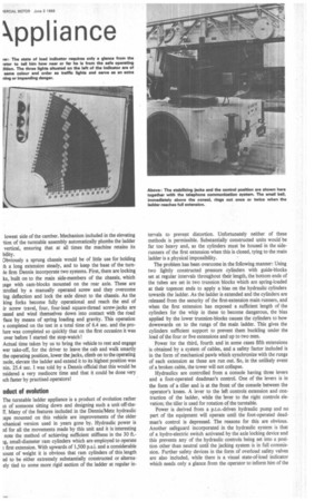
small-diameter ram cylinders which are employed to operate : first extension. With upwards of 1,500 p.s.i. and a considerable bunt of weight it is obvious that ram cylinders of this length ed to be either extremely substantially constructed or alternaely tied to some more rigid section of the ladder at regular in
tervals to prevent distortion. Unfortunately neither of these methods is permissible. Substantially constructed units would be far too heavy and, as the cylinders must be housed in the siderunners of the first extension when this is closed, tying to the main ladder is a physical impossibility.
The problem has been overcome in the following manner: Using two lightly constructed pressure cylinders with guide-blocks set at regular intervals throughout their length, the bottom ends of the tubes are set in two trunnion blocks which are spring-loaded at their topmost ends to apply a bias on the hydraulic cylinders towards the ladder. As the ladder is extended and the cylinders are released from the security of the first-extension main runners, and when the first extension has exposed a sufficient length of the cylinders for the whip in these to become dangerous, the bias applied by the lower trunnion-blocks causes the cylinders to bow downwards on to the rungs of the main ladder. This gives the cylinders sufficient support to prevent them buckling under the load of the four or five extensions and up to two men.
Power for the third, fourth and in some cases fifth extensions is obtained by a system of cables, and a safety factor included is in the form of mechanical pawls which synchronize with the rungs of each extension as these are run out. So, in the unlikely event of a broken cable, the tower will not collapse.
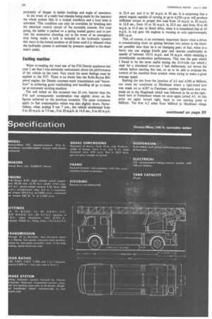
Hydraulics are controlled from a console having three levers and a foot-operated deadman's control. One of the levers is in the form of a tiller and is at the front of the console between the operator's knees. A lever to the left controls extension and contraction of the ladder, while the lever to the right controls elevation; the tiller is used for rotation of the turntable.
Power is derived from a p.t.o.-driven hydraulic pump and no part of the equipment will operate until the foot-operated deadman's control is depressed. The reasons for this are obvious. Another safeguard incorporated in the hydraulic system is that of a hydro-electric switch activated by the axle locking device and this prevents any of the hydraulic controls being set into a position other than neutral until the jacking system is in full commission. Further safety devices in the form of overload safety valves are also included, while there is a visual state-of-load indicator which needs only a glance from the operator to inform him of the proximity of danger in ladder loadings and angle of operation.
In the event of a really bad mistake being made by the operator the whole system fails to a locked condition and a loud siren is activated. This condition can only be overidden by breaking into the electrical control circuit of the turntable console. For road going, the ladder is parked on a spring loaded gantry and to prevent the extensions shooting, out in the event of an emergency stop being made, a lock is included in the hydraulic system; this stays in the locked position at all times until it is released when the hydraulic system is activated by pressure applied to the deadman's pedal.
Exciting machine When re-reading my road test of the F36 Dennis appliance last year I see that 1 was extremely enthusiastic about the performance of the vehicle on the road. Very much the same feelings must be applied to the F37. There is no doubt that the Rolls-Royce B81 petrol engine, the Dennis constant-mesh transmission and "knowhow" in achieving good roadholding and handling all go to make up an extremely exciting machine.
The unit tested on this occasion was 26 cwt. heavier than the F36 and consequently acceleration was slightly down on the figures achieved on the previous occasion. The same comments apply to fuel consumption which was also slightly down. Nevertheless, when scaling 9 ton 7 cwt., the vehicle accelerated from 0 to 20 m.p.h. in 7.9 sec., 0 to 30 m.p.h. in 14.9 sec., 0 to 40 m.p.h. in 25.4 sec. and 0 to 50 m.p.h. in 39 sec. It is surprising that a petrol engine capable of turning at up to 4,250 r.p.m. will produce sufficient torque to propel this load from 10 m.p.h. to 20 m.p.h. in 12.8 sec., from 10 to 30 m.p.h. in 25.9 sec. and from 10 to 40 m.p.h. in 41.6 sec. in direct drive, when it is considered that at 10 m.p.h. in top gear the engines is running at only approximately 800 r.p.m.
This, of course, is an extremely important factor when a driver is concentrating more on getting between two points in the shortest possible time than he is on changing gear; in fact, when in a hurry one can engage fourth gear and operate comfortably at speeds of between 10/15 m.p.h. and 56 m.p.h. whilst retaining a considerable acceleration performance. This was the gear which I found to be the most useful during the 25.9-mile run which I used for a simulated turn-out. I had deliberately not driven the vehicle before starting this test, so as to be able to evaluate the control of the machine from scratch when trying to make a good average speed.
Starting the test from the junction of A3 and A286 at Milford, our route lay southwest to Hindhead where a right-hand turn was made on to A287 to Farnham; another right-hand turn was made on to the Hogsback which was followed as far as the righthand turn to Puttenham where we once again joined A3. At this point we again turned right, back to our starting point at Milford. The first 6.2 miles from Milford to Hindhead village uphill almost all the way, and there were some fairly tructive traffic conditions. In spite of this and the fact that this the first time that I had driven the machine I was able to cover first part of the run in 9 min. 50 sec. at an average speed of 75 m.p.h., which gives some idea of the characteristics of the 7. On the journey to Farnham speeds between 40 and 65 m.p.h. re maintained where possible, with the clock registering close 70 m.p.h. on the stretch of road through Frensham Ponds.
reaching Farnham and joining the Hogsback road we had to in line with a queue of slow-moving traffic for the whole tance back to Puttenham. An Atkinson with 6LX Gardner ited our speed to almost exactly 40 m.p.h. on all the straight etches of this road, and it was not until we rejoined A3 at :tenham that we were able to let the appliance have its head again. The last stretch back to Milford was indeed iilarating, with the clock reading between 68 and 72 m.p.h. most of the way.
The 25.9-mile journey was covered in a total time of 42 min. sec., and an average speed of 36.9 m.p.h. was achieved. Fuel lsumption checked on this run proved to be 5.7 m.p.g.
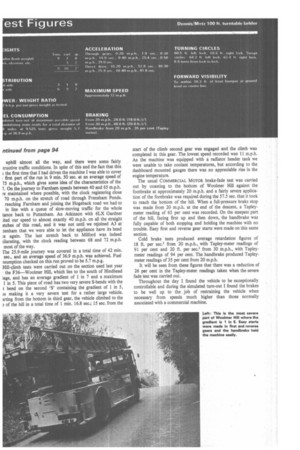
Hill-climb tests were carried out on the section used last year
the F36—Woolmer Hill, which lies to the south of Hindhead tage, and has an average gradient of 1 in 7 and a maximum 1 in 5. This piece of road has two very severe S-bends with the t bend on the second 'S' containing the gradient of 1 in 5, fs making it a very severe test for a rather large vehicle. Irting from the bottom in third gear, the vehicle climbed to the
of the hill in a total time of 1 min. 16.8 sec.; 15 sec. from the start of the climb second gear was engaged and the climb was completed in this gear. The lowest speed recorded was 11 m.p.h. As the machine was equipped with a radiator header tank we were unable to take coolant temperatures, but according to the dashboard mounted gauges there was no appreciable rise in the engine temperature.
The usual COMMERCIAL MOTOR brake-fade test was carried out by coasting to the bottom of Woolmer Hill against the footbrake at approximately 20 m.p.h. and a fairly severe applica tion of the footbrake was required during the 57.5 sec. that it took to reach the bottom of the hill. When a full-pressure brake stop was made from 20 m.p.h. at the end of the descent, a Tapley meter reading of 65 per cent was recorded. On the steepest part of the hill, facing first up and then down, the handbrake was fully capable of both stopping and holding the machine with no trouble. Easy first and reverse gear starts were made on this same section.
Cold brake tests produced average retardation figures of 18 ft. per sec.' from 20 m.p.h., with Tapley-meter readings of
91 per cent and 20 ft. per sec.2 from 30 m.p.h., with Tapleymeter readings of 94 per cent. The handbrake produced Tapleymeter readings of 35 per cent from 20 m.p.h.
It will be seen from these figures that there was a reduction of 26 per cent in the Tapley-meter readings taken when the severe fade test was carried out.
Throughout the day I found the vehicle to be exceptionally controllable and during the simulated turn-out I found the brakes to be well up to the job of restraining the vehicle when necessary from speeds much higher than those normally associated with a commercial machine.