


A NEW PETROL-ELECTRIC MOBILE CRANE.
Page 9
If you've noticed an error in this article please click here to report it so we can fix it.
The Loading and Unloading of any Goods Transport Unit are Greatly Facilitated by the Use of Suitable Appliances Such as That Described.
ir ANY EFFORTS have been devoted, IY..I.some with a considerable, measure of success, to the development of a satisfactory form of mobile crane which can be used in any situation where the road crust, or other surface on which the ap.pliance is requized to 'work, is in a fairly
good condition. Such machines have already proved their value in docks, large warehouses and in factories where heavy materials have to be handled. So far, the best. type has been the batteryelectric, in which the electricity is employed both for travelling and for the operation of the crane. The one disadvantage of this is the recharging of the battery.
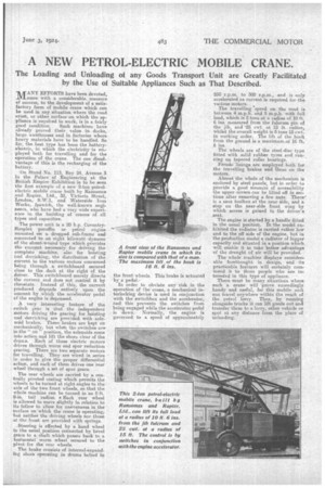
On Stand No. 113, Bay 24, Avenue 3 in the Palace of Engineering at. the British Empire Exhibition is to be seen the first example of a new 2-ton petrolelectric mobile crane built by Ransomes and Rapier. Ltd., 32, Victoria Street, London, S.W.1, and Waterside Iron Works, Ipswich, the well-known engineers, who have had a very wide experience in the building of cranes of all types and capacities.
The power unit is a 20 h.p. CoventrySimplex paraffin or petrol engine mounted on a dropped sub-frame and connected to an eight kilowatt .dynamo of the shunt-wound type which provides the current necessary for driving the complete machine, also for hoisting and derricking, the distribution of the current to the various motors concerned being through a switchboard secured close to the dash at the right of the driver. This switchboard merely directs the current and does not control it by rheostats. Instead of this, the current produced depends entirely upon the amount by which the accelerator pedal of the engine is depressed.
A very interesting feature of the switch gear is that the independent motors driving the gearing for hoisting and -dorricking are provided with solenoid brakes. These brakes are kept on mechanically, but when the.switches are in the " on ' position, the solenoids come into action and lift the shoes clear of the : drums. Each of these electric motors drives through worm and spur reduction gearing. There are two separate motors for travelling. They are wired in series in order to give the proper differential action' and each of them drives one rear wheel through a set of spur gears.
The rear wheels are carried by a. centrally pivoted casting which permits the wheels to be turned at right angles to the axis of the two front wheels, so that the whole machine can be turned in an 8-ft. 0-in, tail radius. • Each rear wheel is allowed to move slightly in relation to its fellow to allow for unevenness in the kurface on which the crane is operating, hut neither the driving wheels nor those at the front are provided with springs.
.Steering is effected by a hand wheel in the usual position connected by bevel gears to a shaft which passes back to a horizontal worm .wheel seamed to the pivot for the rear wheels.
The brake consists of internal-expanding shoes operating in drums bolted to the front wheels. This brake is actuated by a pedal. In order to obviate any risk in the operation of the crane, a mechanical interlocking device is used in conjunction with the switchbox and the accelerator, and this prevents the switches from being engaged while the accelerator pedal is down. Normally, the engine is governed to a speed of approximately 250 r.p.m. to 300 r.p.m., and is only accelerated as current is required for the various motors.
The travelling speed on the road is between 4 m.p.h. and 5 m.p.h. with full load, which is 2 tons at a radius of 10 ft. 6 ins, measured from the fulcrum pin of the jib, and '25 cwt. at 15 ft. radius, whilst the overall weight is 5 tons 15 cwt. in working order. The lift of the hook from the ground is a maximumsof 16 ft. 6 ins.
The wheels are of the steel-disc type fitted with solid rubber tyres and run. nil]," on tapered roller bearings.
ierodo linings are employed both for the travelling brakes and those on the motors.
Almost the whole of the mechanism is enclosed by steel panels, but in order to provide a good measure of accessibility the upper covers can be lifted off in sections after removing a few nuts. There' is a neat toolbox at the near side, and a step on the nearside front wing by which access is gained to the driver's seat.
The engine is started by a handle fitted in the usual position. In the model exhibited the radiator is carried rather low and to the off side or the engine, but in the production model a radiator of bigger capacity and situated in a position which will enable it to take bother advantage of the draught of air will be provided.
The whole machine displays consider-. able forethought in design, and its practicable features will certainly corn.mend it to those people who are interested in this type of appliance. There must be many situations where such a crane will 'prove exceedingly handy and useful, for this mobile unit can travel anywhere within the reach of the petrol lorry. Thus, by running alongside trucks it can lift goods out and transfer them to a lorry, other vehicle or spot at any distance from the place of unloading.