


AN ENTIRELY NEI „EY BUS CHASSIS.
Page 54
Page 55
Page 56
Page 57
If you've noticed an error in this article please click here to report it so we can fix it.
A Sturdy Model for 32-34-seater Bodii Chat ward Design and Interesting Features yout.
A LT-HOUGH the works of Crossley Motors. Ltd., IA. at Gorton, Manchester, has not of recent years been responsible for the production of a chassis suitable for ordinary commercial use, it must not be assumed that knowledge of this branch of automobile 'work is therefore lacking anyway. The private cars produced by the company have attained world-wide repute as high-grade examples of British motorcar practice, whilst, on the other side of the picture, the concern has produced, and is still producing, many vehicles for the British War Department which, by the very nature of things, must be of the heavy duty type. Big rigid-frame six-wheelers, tractors and so on, haye all come within the scope of the company's works, so that the introduction of a commercial chassis, although something of a departure from recent practice, does not really
strike an entirely new -note or cause us surprise.
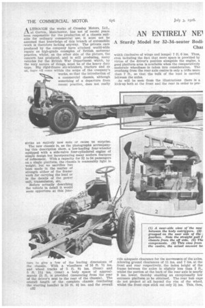
The new chassis is, as the photographs accompanying this description show, a low-loading four-wheeler equipped with a side-valve four-cylindered engine of simple design but incorporating many modern features of refinement. With a capacity for 32 to 34 passengers on a single platform, the chassis is reasonably light in weight, but no sacrifice has been made in the matter of strength -either of the framework for carrying the load or in the details of the power unit, transmission, etc.
Before actually describing the vehicle in detail it would seem opportune at this junc ture to give a few of the leading dimensions of the chassis. With a wheelbase of 16 ft. 7 ins. and wheel tracks of 5 ft, 8-i ins. (front) and 5 ft. 111 ins. (rear) a body space of approximately 21 ft. is provided (measuring from the rear of the driver's seat to the rear of the chassis). The overall length of the complete chassis (excluding the starting handle) is 25 ft. 4i ins, and the overall c32 width (inclusive of wings and lamps) 7 ft. 6 ins. Thus, even including the fact that more space is provided by virtue of the driver's position alongside the engine, a good platform area is available when the comparatively moderate wheelbase is taken into consideration. The overhang from the rear axle centre is only a trifle more than 7 ft., so that the bulk of the load is carried between the axles.
As will be seen from the illustrations there is a kick-up both at the front and the rear in order to pro vide adequate clearance for tlrmovemeonts of the axles. Allowing ground clearances of 11 ins. and 7 ins, at the front and rear respectively, the laden height of the frame between the axles is slightly less than 2 ft., whilst the portion at the back of the rear axle is nearly 9 ins, lower, thereby enabling an exceptionally low entrance platform to be obtained. The rear hub caps do not project at all beyond the rim of the wheel, whilst the front caps stick out only 21 ins. This, then, gives a fair idea of the size and the capacity of the chassis. We will now turn to a consideration of the various units used in the make-up of the vehicle in more detail.
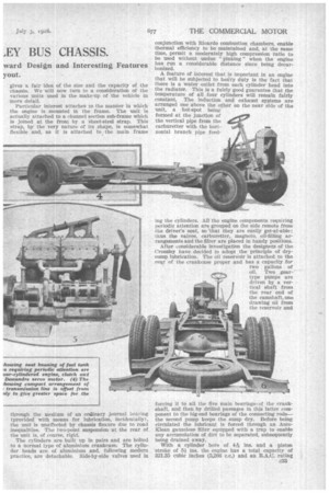
Particular interest attaches to the manner in which the engine is mounted in the frame. The unit is actually attached to a channel section sub-frame which is joined at the front by a sheet-steel strap. This strap, by the very nature of its shape, is somewhat flexible and, as it is attached to the main frame through the medium of an ordinary journal bearing (provided with means for lubrication, incidentally), the unit is unaffected by chassis flexure due to road inequalities. The two-point suspension at the rear of the unit is, of course, rigid.
The cylinders are built up in pairs and are bolted to a normal type of aluminium crankcase. The cylinder heads are of aluminium and, following modern practice, are detachable. Side-by-side valves used in conjunction with Ricardo combustion chambers, enable thermal efficiency to be maintained and, at the same time, permit a moderately high compression ratio to be used without undue "pinking" when the engine has run a considerable distance since being decarbonized.
A feature of interest that is important in an engine that will be subjected to heavy duty is the fact that there is a water outlet from each cylinder head into the radiator. This is a fairly good guarantee that the temperature of all four cylinders will remain fairly constant. The induction and exhaust systems are arranged one above the other on the near side of the unit, a hot-spot being formed at the junction of the vertical pipe from the carburetter with the horizontal branch pipe feed
ing the cylinders, . AU the engine components requiring periodic attention are grouped on the side remote from the driver's seat, so thatthey are easily get-at-able; thus the valves, carburetter, magneto, oil-filling arrangements and the filter are placed in handy positions.
After considerable investigation the designers of the Crossley have decided to adopt the •principle of drysump lubrication. The oil reservoir is attached to the rear of the crankcase proper and has a capacity for two gallons of oil. Two geartype pumps are driven by a vertical shaft from the rear end of the camshaft, one drawing on from the reservoir and forcing it to all the five main bearings i of the crankshaft, and then by drilled passages in this latter component to the big-end bearings of the connecting rods— the second pump keeps the sump dry. Before being circulated the lubricant is forced through an AutoKlean gauzeless filter equipped with a trap to enable any accumulation of dirt to be separated, subsequently being drained away.
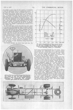
With a cylinder bore of zIA ins, and a piston stroke of 51 ins. the engine has a total capacity of 321.35 cubic inches (5,266 c.c.) and an R.A.C. rating c33
of 29.8 li.p. Particular care has been taken in the layout of the induction system to attain a high torque figure at comparatively low rates of revolution speed. This characteristic is quite clearly shown in the power curve which will be found among the illustrations accompanying this article. The maximum power of 70 b.h.p. is developed at about 2,250 r.p.m., whilst at the point of maximum torque-1,000 r.p.m.—practically 48 b.h.p. is available, which IS equivalent to a brake mean effective pressure of 110 lb. per sq. in.— an excellent showing and ideally suited to the work for which the unit is intended.
The clutch is of the single-plate type, actuated through the medium of toggle levers in order to give a light pedal pressure; there is a disc-type clutch stop. A very simple arrangement is used for the operation of the gears; a right-hand lever moving in a gate operates a cross-shaft through t ie medium of a crosspin type joint. This cross-shaft can be moved laterally and can be oscillated to and fro. The motion is transmitted to the •striking forks in the gear-box by means of a stout tubular shaft located in spherically seated housings and fitted with ball joints at the points of attachment at the front and rear. The system works sweetly, has no back-lash and is very simple in layout—three attributes which, usually, are difficult to combine.
The gearbox is held in a sub-frame which is attached to the chassis at three points. Four speeds are provided, the "gearbox reductions being 5,884 to 1, 3.29 to 1 and 1.88 to 1 for the three indirect gears respectively. With a 7-to-1 rear axle reduction ratio, the overall reductions—engine to road wheels— are 1st speed 41.188 to 1, 2nd 23.037 to 1, 3rd 13.18 to 1 and 4th 7.00 to 1. There is one feature regarding the gear
box which is worthy of comment. By taking off one cover from the rear of the box and withdrawing the sliding shaft, all the gears can be lifted out through a large inspection cover on the top. The layshaft, incidentally, will come out through the same end cover, thus making the job of dismantling this unit of the transmission very simple.
The drive is transmitted to the rear axle by a twostage open propeller shaft, fitted with three triple flexible joints. The forward shaft is supported at its rear end by a large self-aligning ball-bearing. The rear axle is of the underslung-worm type with a bevel Pinion differential. The axle shafts are fully floating, and can be withdrawn for examination or replacement when the wheels are on the ground.
The layout for the braking System is of particular
interest in that only one cross-shaft is used.is thought that by using a multiplicity of levers, ranks and shafts a great deal a lost motion is developed, a line of reasoningWhich is undoubtedly sound. A rod from the pedal exerts a straight pull on to a Dewandre servo motor bolted direct to the outside of the frame immediately behind and below the driver's seat. A further rod, from the rear of the servo, communicates with a swinging lihk mounted on a crossshaft situated about mid-way along the chassis. For the rest, the operation is on quite straightforward lines. The front brakes, also operated by the pedal and servo motor, are contained in drums of 181? ins. diameter (the rear drums are 20 ins. in diameter). The hand lever applies a separate set of shoes in the _rear drums only.
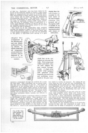
To give some idea of the care that has been taken in the layout of the frame in order to obtain rigidity, it might be mentioned that the depth of the side members is no less than 8,1, ins, which, combined with the facts that the top and bottom flanges are 3 ins, wide and the members themselves are in, thick, makes it obvious that for its load the structure is immensely strong. There are seven heavy cross-meinbers, and 12 double-channel-section outrigger brackets of pressed steel form. the platform upon which is mounted the body framework. Hard rubber pads are interposed between the two elements—the body structure and the chassis—to give a small amount of resiliency and to avoid vibrations of high frequency being 'transmitted from the chassis. • Semi-elliptic springs are fitted front and rear, the latter being underslung beneath the axle casing. These rear springs are constructed with a special divided master leaf and a stress block to provide high resistence to driving torque and braking reaction. Both front and rear springs are tongued and grooved into the spring seats on their respective axles.
Equipment includes 36-in. by 6-in, straight side Dunlop pneumatic tyres, single wheels being fitted to the front and twins at the rear; the spare, incidentally, is carried in a well which is formed between the frame members at the rear of the chassis. The lighting and starting equipment works on a 12-volt circuit, with 110 ampere-hour accumulators. The capacity of the dynamo and battery is sufficient for eight interior lamps, two route indicator lamps and one dash lamp, in addition to the ordinary driving lamps, i.e., two headlamps, two side lamps and a rear lamp.
In conclusion, it might not be out of place to give a few particulars with regard to the performance of the vehicle under test. Slightly overloaded, 50 m.p.h. has been attained which, discounting a trifle for the extra wind resistance occasioned by a bus body, would mean to say that a genuine 45 m.p.h. should be possible at any time under reasonably favourable conditions. Similarly loaded, the fuel consumption on a straight run worked out at over 10 m.p.g. The chassis weight unladen is 2 tons 16i cwt.