


HINTS ON MAINTENANCE.
Page 26
Page 27
If you've noticed an error in this article please click here to report it so we can fix it.
How to Get the Best Out of a Vehicle, to Secure Reliability and to Avoid Trouble.
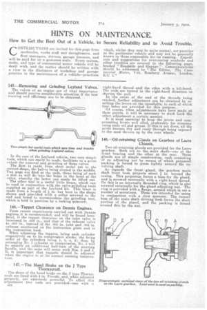
145.—Removing and Grinding Leyland Valves. The valves of an engine are of vital importance and should receive considerable attention if the best running and efficiency are to be obtained.
In the case-of the Leyland vehicle, two very simple tools, which can easily be made, facilitate to a great extent the removal and grinding of these valves. • The first is made from sheet metal cut to the correct shape, the halves being riveted in the middle. Two pegs are filed at the ends, these being of such a size as will fit into the holes in the head of the valve, whereby the latter can easily be lifted out. The other tool is a useful little brace, which can be used in conjunction with the valve-grinding tools supplied as part of the Leyland kit. This brace is made from a length of in. bar bent to the shape shown and provided with a collar screwedto the end and bored to accommodate the grinding tool, which is held in position by a lacking setscrew.
146.—Tappet Clearance on Dennis Engines. From recent experiments carried out with Dennis engines it is recommended, and will be found beneficial, if the tappet clearance on the inlet valve is increased. to in., and that of the exhaust valve to .010 in., instead of the .003 in. inlet and .005 in. exhaust mentioned on the instruction plate and in the instruction book. When adjusting the tappets, bring each cylinder• respectively on to its compression stroke, the firing order of the cylinders being 1, 3, 4,, 2; thus, by arranging No. 1 cylinder on compression., No. 3 will exactly an additional half-turn of the starting handle, and the same will occur with Nos. 2 and 4. It is important that tappets should be adjusted when the engine is at its normal running temperature.
147.—The Hand Brake on the J Type Thornycroft. The shoes of the band brake on the J type Thornycroft are lined with i• in. Ferodo, and, when adjusted properly, are extremely powerful. To effect this adjustment two rods are provided—one with a right-hand thread and the other with a left-hand. The rods are turned in the right-hand direction to shorten the pull. • In the event of the end of the threads being reached, further adjustment can be obtained by resetting the levers on the camshafts, in each of which four holes are provided for this purpose. Of course, when adjustments have been made at these points, it will be necessary to slack back the other adjustment a certain amount. It is most essential to keep the joints and compensating levers well oiled, preferably for economy using stale oil and grease. If this is not done, all the perts become dry and rusty through being exposed to the mud thrown up by the rear wheels.
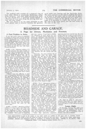
148.—Oil-retaining Glands on Gearbox of Lacre, Chassis.
Two oil-retainirig glands are provided for the Lacre gearbox. Both are on the main shaft—one at the front bearing and the other at the rear. These glands are of simple construction, each consisting of an adjusting nut by means of which prepared packing is forced to press tightly around the revolving shaft. As regards the front gland, the gearbox main shaft front bush projects about -1 in. beyond the casing. This projection forms a base for the gland, and is screwed externally with a right-hand thread. On this is an internally threaded ring, which is alsO screwed externally for the gland adjusting nut. The ring is provided with .a flange, around which is cut a number of serrations. These are intended for using in conjunction with a claw spanner. The turned boss of the main shaft driving fork forms the shaft portion of the gland, and the packing is forced around this by the nut. The packing used consists of a prepared ring of lead wool, which is practically frictionless under great pressure. The main shaft driving fork holdin.. nut should have a grommet wound behind it, otKerwise oil may pass along the driving fork keyway and thus escape.
The rear gland is on the same principle as the front gland, and is situated between the gearbox mad shaft rear bearing and the foot-brake drum. The ame material is also used in packing this gland as i used in the other, and in each•case the gland nut a prevented from slacking back by a small clip.
To remove either of the glands to fit, new packings, it is necessary to remove the driving fork in the ass of the front gland and the foot brake in the case of the rear.