


New Air Suspension System
Page 9
If you've noticed an error in this article please click here to report it so we can fix it.
Firestone Company Evolves Ingenious Pneumatic Springing Device, Suitable for Independent SusPension and Incorporating Automatic Control
DURING the history of the motor vehicle, few attempts have been made to depart from the use of steel springs in suspension. systems. Whilst rubber and air are successfully employed in confined field's, more haa been done in endeavours to improve the action of steel-spring systems by the addition of shock absorbers,, rebound dampers, stabilizers, etc. Such devices are highly effective, but they do not represent a solution to the problem by getting to the root of the. matter.
In view of the foregoing, it is of great interest to rearm that a pneus matic system, which appears to possess certain advantages that every student of suspension will appreciate, has been developed and patented (Specification No. 473,971) by the Firestone Tyre and Rubber Co., Ltd., Great West Road, Brentford,• Middlesex.
Variable Volume.
. • A bellows comprises, in this device, the supporting medium between wheel and frame. It is normally in communication with an air reservoir so that the total volume of the contents of both is available to serve in a cushioning capacity. Between the bellows and the reservoir, however, is a valve which has several important functions.
Chief of these is its ability to close the passage to. the reservoir when the hbrizcmtal velocity of the vehicle changes, as by acceleration, retardation or cornering. This results in the reactionary force being taken by only the bellows, and, in consequence, the resistance , being considerably higher than When the load is shared between both vessels. Accordingly, pitching caused by braking and acceleration, and rolling through cornering, are reduced.
Besides this function, the valve slows the recoil from ordinary road shocks. Whilst permitting ,free flow of air. froni the bellows to the 'i-e• ervoir., it, restricts the paSSage of the mediurr in' the reverse direction. Thus, there' is reSistonce to the initial force, but • no corresponding return pressure.
Pendulum Control.
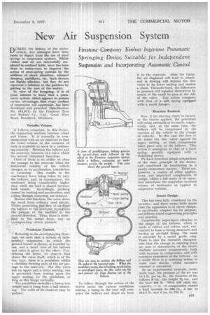
Referring to the accompanying drawings,.' We note that a' system.. of independent suspension, in . which the general. layout is-shown, is revealed by one, and a detail view of the bellows and valve is given by the other. Considering the latter, we observe that above the valve itself, which is of the disc type, there is a pendulum within a chamber forming part of the air passage to the reservoirThe disc valve has an upper and a lower seating, but is prevented from resting upon the upper seating, by the pendulum, so long as this hangs vertically.
'The penclultun embodies a heavy bob weight and is hung from a ball mounting. The walls of its chamber may be . 'padded. it to the reservoir. After the bump, the air displaced will tend to return, and in flowing will depress the disc valve to itslower seating and receive a check. Thenceforward, the differences in pressure will equalize themselves by means of the small by-pass at the side of the valve. This action compares with that of a soft spring equipped with a recoil damper.
Reaction Resisted.
Now, if the steering wheel be turned, or the brakes applied, the pendulum will swing outwards or forwards, respectively, and, at the sametime, the bellows Will be compressed by the reaction of the vehicle to the change of velocity. In this case the flow of air raises the disc valve against its upper seating, so that compression takes place only in the bellows. This action is analogous to that qf a hard spring, possibly equipped with a stabilizing device.
We have described simple adaptations of the basic principle of the device, and considered its functioning in a purely elementary manner. There are. however, a variety of other applications, and important complexities of design, whilst a full study of its operation introduces the somewhat involved science of mechanics as applied to suspension systems, Sound Design.
This has been fully considered by the inventor, and there seems little doubt that the apparatus is of clever design, is excellently adapted for its purpose, and follows sound engineering principles and practice. Considerable importance attaches to the shape of the bellows, which is made of rubber and cotton cord, vulcanized to form a strong structure, and having an air-tight lining. The waist is encircled by a metal girdle ring. There is also the desirable characteristic that the change in resisting force per unit of deformation of the elastic medium increases progressively both
with increase in compression and with excessive expansion of the bellows. As a result there is a snubbing action to resist road shocks, whilst excessive rebound is prevented.
In an experimental example, under static load, the pressure of the air was 14.1 lb. per sq. in., the diameter of this bellows 8 ins., the height 7/. ins., and the load 400 lb. With 450 cubic ins. capacity, 1 in. of compression caused a load increase to 500 lb., 2 ins. to 612.5 lb. and 3 ins. to 725 lb.