


New Engine for Low-grade Fuel
Page 32
If you've noticed an error in this article please click here to report it so we can fix it.
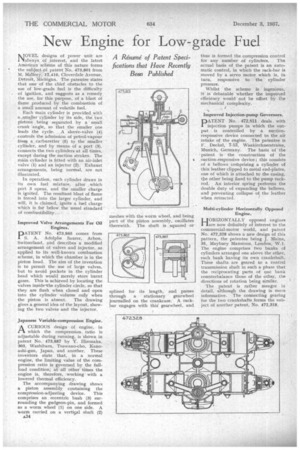
A Résumé of Patent Specifications that Have Recently Been Published NOVEL designs of power unit are always of interest, and the latest Amedcan scheine of this nature forms the subject of patent No. 473,801 from M. Mallory, -12,416, Cloverdale Avenue, Detroit, Michigan. The patentee states that one of the chief obstacles to the use of low-grade fuel is the difficulty of ignition, and suggests as a remedy, the use, for this purpose, of a blast of flame produced by the combustion of a small amount of volatile fuel.
Each main cylinder is provided with a..,.srnaJler cylinder by its side, the. two pistons being separated by a small crank angle, so that the smaller one leads the cycle, A sleeve-valve (4) controls the admission of petrol-vapour frorn a. carburetter (5) to the smaller cylinder, and by means of a port (3), connects the two cylinders at all tithes, except during the suction strokes. The main cylinder is fitted with an air-inlet valve (I) and an injector (2). Exhaust arrangements, being normal, are not illustrated.
In operation, each cylinder draws in its own fuel mixture, after . which port 3 opens, and the smaller charge is ignited. The resultant blast of flame is forced into the larger cylinder, and will, it is claimed, ignite a fuel charge which is far below the usual standard of combustibility.
Improved Valve Arrangements For Oil Engines.
PATENT No, 473,865 comes from S. A. Adolphe Saurer, Arbon, Switzerland, and describes a modified arrangement of valves and injector, as applied to its well-known combustion scheme, in which the chamber is in the piston head. The aim of the invention is to permit the use of large valves, but to avoid pockets in the cylinder bead which would merely store burnt gases. This is achieved by locating the valves insidOthe cylinder circle, so that they are flush when closed and open into the cylinder volume only when the piston is absent. The drawing gives a general idea of the layout, showing the two valves and the injector.
Japanese Variable•cornpression Engine.
ACURIOUS design of engine, in which the compression ratio is adjustable during running, is shown in patent No. 473,887 by Y. Hironaka, 303, Washibara, Tsuwano-cho, Kanoashi-gun, Japan, and another. These inventors state that, in a normal engine, the limiting value of the compression ratio is governed by the full. load condition; at all other times the engine is, therefore, workingwith a lowered thermal efficiency.
The accompanying drawing shows a piston assembly containing the compression-adjusting device. This comprises an eccentric bush (3) surrounding the gudgeon-pin, and formed as a worm wheel (1) on one side. A worm carried on a vertis,a1 shaft (2)
A34
thus is formed the compression control for any number of cylinders. The actual basis of the patent is an automatic control, in which the rack-bar is moved by a servo motor which is, in. turn, responsive to .the cylinder pressure.
Whilst the scheme is ingenious, it is debatable whether the improved efficiency would not be offset by the mechanical complexity.
Improved Injection-pump Governors, PATENT No. 472,811 deals with injection pumps in which the output is controlled by a suctionresponsive device connected to the air intake of the engine. The patentee is F. Deckel, 7-13, Wa,akirchnerstra.sse, Munich, Germany.. The basis of the • patent is the construction of . the suction-responsive device; this consists of a bellows cothprising a cylinder of thin leather clipped to metal end-plates, one of which is attached to the casing, the other being fixed to the pump rackrod. An interior, ,S.pring performs the double duty of expanding the bellows, and preventing collapse of the leather when retracted.
Multi-cylinder Horizontally Opposed
Engine.
HORIZONTALLY opposed engines are now definitely of interest to the commercial-motor world, and patent No. 472,328 shows a new design of this pattern, the patentee being J. Maina, 35, Maybury Mansions, London, V. I. The engine comprises two banks of cylinders arranged one above the other, each bank having its own crankshaft. These shafts are geared to a central transmission shaft in such a phase that the reciprocating parts of one bank counterbalance those of the other, the directions of rotation being similar.
The patent is rather meagre in detail, although the drawing is mora informative. The connecting gearing for the two crankshafts forms the subject of alio-LI-ler patent, No. 472,318,