


Patents Completed.
Page 20
If you've noticed an error in this article please click here to report it so we can fix it.
Nifolseley Body Suspension. Fowler Self-propelled Ploughs. Foden Wheels.
A. J. SALOMON, No. 8860 of 1014 dated 25th October, 1913.— This specification describes a carburetter which operates partly as a jet carburetter and partly as a surface carburetter. The surface carburetter gives a weaker mixture at high speeds,
while a jet carburetter acts in the opposite way, and by combining the two a uniform mixture is obtained.
In the construction illustrated, fuel is supplied, by a channel near the bottom on the left-hand side, to a vertical jet mounted in a conical choke-tube. A tubular throttle-valve is moved up and down over the choke-tube to control the passage to the induction pipe at the upper right-hand side. The main air supply is admitted at the bottom through a central constant opening and a ring of variable openings round it. Above the air-inlet is fixed an inverted cone of wire gauze, and petrol is allowed to fall on this gauze through a small aperture in a plug vertically below the jet. A needle-valve fixed in the throttle passes downwards through the jet and controls the small aperture mentioned above, so that when the throttle is closed, i.e. in its lowest position, the needle enters the plug and prevents fuel from escaping on to the gauze.
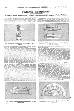
R. H. FOWLER, H. COOPER AND A. PEPPER, No. 24,335, dated 27th October, 1913.—This specification describes a motor plough constructed so that the tool-carrying frame can be raised and the ploughing tools brought out of the ground. The rear end of the tool-carrying frame is hinged to the carriage. By means of a lever centred on the motor the cross-head which carries the ploughshares can be raised so a to lift the front end of the frame.
The tail end of the tool frame is supported by a castor wheel, the stem of which is carried by a bracket which is attached to or extended from the frame. When the front end of the frame is raised, there is a tendency for the hind end to be depressed, so that the castor wheel, owing to the swinging of the frame and bracket, assumes a forward position, and the hinge, about which the bracket turns, rises, carrying with it the tool-carrying frame and the main frame. THE WOLSELEY TOOL AND MOTOR CAR CO., LTD., AND A. A. lipmcgoros, No. 27,702, dated 2nd December, 1913.—A method of supporting the bodies of vehicles from their axles by springs of which the rolling is controlled by springs other than those which control the vertical oscillations, is described in this specification. In the construction illustrated a semi-elliptic spring on each side of the vehicle controls the vertical movement of the body in relation to the axle. To a transverse bar carrying the bearings and the frame there are rigidly connected arms formed as springs, and the outer ends of these arms project over the middles of the elliptic springs and are there connected by means of links with the axle. Under ordinary vertical movements of the frame in relation to the axle, the spring arms connected to the transverse bar exert no in fluence upon the spring suspension. When rolling takes place, the spring arm at one side of the frame tends to yield upwards, and that at the other side of the frame downwards, so that the rolling is automatically resisted.
FODENS Ian. AND E. R. FODEN, No. 3769, dated 13th February, 1914.—This specification describes wheels for heavy motor wagons in which the tightening up of the tire can be effected easily and without taking off the wheel.
The hub of the wheel, which is preferably made of cast steel, is provided with radial sockets screwed either internally or externally, and into these sockets fit tubular spokes, which can be locked in position by nuts provided with tommy holes, as shown on the four lower spokes. To the outer ends of the spokes, shanks of cast steel or other metal segments are attached, and on these the wooden segments comprising the felloe are mounted, the tire being secured to these latter segments with countersunk bolts. By means of tommy holes or otherwise the spokes can be screwed in or out of the sockets so as to expand the segments and tighten up the tire, or so as to contract the segments in order to enable the tire to be taken off the wheel.