


Patents Completed.
Page 24
If you've noticed an error in this article please click here to report it so we can fix it.
CONTACT BREAKER.—Guy and Another.—No. 23,957, dated 30th October, 1907.—This contact breaker is so constructed that all the parts can readily be removed or replaced. To the base (2) is attached the contact-breaker ring (31, which is made of insulating inaterial. This ring is attached to the base by means of studs (4) arranged at unequal distances apart to ensure the ring being replaced in the same position. Secured to the spindle (6i is an arm (7) terminat ing in a head (9) which acommodates brush or plunger (8) electrically connected to the arm (7) by means of a wire (1)a The plunger (8) is forced radially outwatd by a spring (11) secured to the boss (141 by means of a nut (13). A coves plate (5) carries inwardly-projecting plugs (171 which are split and which fit into
holes (17a) in the segments (18). The cover plate is attached by nuts (20) screwed on to the studs (4).
%VATER INJECTOR FOR INTERNAL-COMBUSTION ENGINE.—Brown. —No. 2,270, dated 1st February, 1908.— This device during the explosion stroke, injects into the cylinder a quantity of water, which is proportional to the pressure within the cylinder. The device consists al a cylindrical casing having a water inlet (A) and a non-return valve (Bi. Within the casing is a hollow piston (D) having an extension (1)11 of reduced diameter. The casing is provided with an external screw-thread (C) by means of which it is secured in the cylinder wall. Between a flange on the piston and a shoulder in the casing is a spring (J1), which tends to keep the piston in the position shown in the illustration. At that end of the piston which extends into the cylinder is arranged a spring-controlled valve (G!. In operation, during
the suction stroke of the engine, the piston (D) will be drawn down into the position shown, and water will be sucked into the upper part (Di) of the piston, past the non-return valve (B). During the compression stroke the non-return valve (B) closes, and the water admitted during the suction stroke is subjected to pressure, and, were it not for the valve (G) which is loaded sufficiently to resist the pressure due to compression, water would flow into the cylinder. When the explosion takes place the pressure rises sufficiently to overcome the spring-controlled valve (Gi, and water, in amount proportional to the excess of pressure and to its duration, enters the combustion space ; the whole piston, meanwhile, moves back.
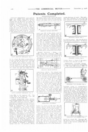
BRAKE SYSTEM. — Miller. — No. 3,487, dated 15th February, 1908.—According to this invention the exhaust gases are utilised to operate the brakes on a motor-driven vehicle. The exhaust pipe (2) from the motor (1) communicates by means of branch pipes (3, 7. Si with cylinders (9) arranged near the brakes and secured /o the frame of the vehicle. At the point where the branch (3) joins the exhaust pipe 1,2), a valve (4) is provided which is arranged to direct the gases either to the branch pipe or to the exhaust box. Within the cylinders (9) are pistons (11), the rods of which are connected by means of cords (14) to the brakes. interposed between a head on the piston rods and the cylinders, are spiral springs (15) which normally keep the brakes free. It will be seen that when the exhaust gases are ditected to the cy tinders by means of the valve (4), the pistons will be forced up the cylinders and the brakes will thus he npplied. A spring-controlled valve (18) is provided, which is so adjusted as to resist a pressure a little greater than the compression.
SPRING SEATS FOR AXLES OF ROAD YEHICLFS.—Butler.—No. 1,055, dated 16th January, 1908.—This invention relates to seats for the connection of springs to axles that are composed of girders. The seat consists of a piece of metal (6), exteucling transversely across the girders 11, 2), and having its ends bent sharply back as at 7, thus forming a double thickness of metal. The ends then bent obliquely as at 8, and agt bent vertically as at 9, so as to be par
lei with the girders. The ends (9) are st ably secured to the girders. In the mo
fication shown in figure 2 the ends ( are bent over and are cut off.
IMPROVED CHASSIS.—Societe Construction de Vehicules Automobiles No. 798, dated 13th January, 1908.—T1 invention relates to commercial-moi vehicles of the delivery-van type, and for its object to provide the maxim' space for the body. The driver's seat perch (21) is situated at the extreme re of the vehicle, and at the side of this sl is arranged the motor (3) having its a parallel with the rear axle. The mot drives the primary shaft of a change-spc gear (4), the casing of which contains I differential and the clutch. The magni (9) and other accessory parts are local ii proximity to the motor, and arc p tected by a hood (10). The part (19) i the steering post is inclined and s cc fleeted to the vertical portion (17) by cardan joint.