


MORE ABOUT THE BRISTOL RE
Page 36
Page 37
If you've noticed an error in this article please click here to report it so we can fix it.
SINCE the report on the Bristol RE rear-engined p.s.v. design was written (page 901 of last week's issue), additional information about this most interesting project has become available following a visit by the Technical Editor to the Bristol works, now in its 50th year of manufacture. This first-hand appraisal of the model revealed a number of original design features.
One of the most striking points of the RE, which has a chassis weight of 4 tons 17 cwt. ready for the road, is the adoption of air suspension at front and rear as standard. Firestone air springs are employed, the pair at the front axle being of a new type, the special seals of which considerably reduce the chance of leakage when a vehicle is standing overnight. These rolling-diaphragm springs work in conjunction with small surge tanks, the designed frequency being 90 cycles per minute irrespective of loading.
The four air springs at the rear are of a slightly different Firestone design and have a basic frequency of 86 c.p.m. Because there is a spring ahead of and behind the rear axle at each side, the rear suspension provides more complete insulation from road shocks than the type of layout which consists solely of long radius arms with bellows at the extreme rear of these arms.
Although no-delay levelling valves have sometimes been considered to be unsuitable by some British vehicle manufacturers, Clayton Dewandre valves of this type are used on the RE, there being one valve at each wheel. This has not been found to produce the type of continuous rolling motion which other designers have feared, and air usage is not excessive. The suspension layout is such, in fact, that even with the bellows at one wheel fully deflated, the loaded chassis has been shown to retain an even keel. Suspension damping, incidentally, is given by Girling telescopic units at the extreme rear of the rear-suspension radius arms, and by Armstrong lever-type equipment at the front axle.
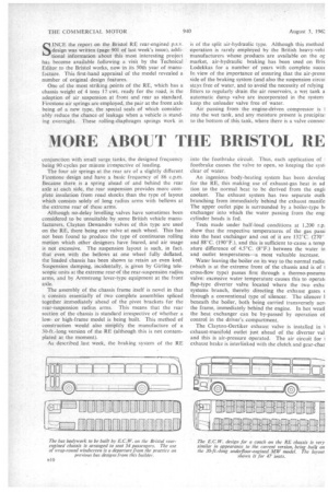
The assembly of the chassis frame itself is novel in that it consists essentially of two complete assemblies spliced together immediately ahead of the pivot brackets for the rear-suspension radius arms. This means that the rear section of the chassis is standard irrespective of whether a lowor high-frame model is being built. This method of construction would also simplify the manufacture of a 30-ft.-long version of the RE (although this is not contemplated at the moment).
As described last week, the braking system of the RE is of the split air-hydraulic type. Although this method operation is rarely employed by the British heavy-vehi manufacturers whose products are available on the or market, air-hydraulic braking has been used on Bris Lodekkas for a number of years with complete succc In view of the importance of ensuring that the air-pressi side of the braking system (and also the suspension circa stays free of water, and to avoid the necessity of relying fitters to regularly drain the air reservoirs, a wet tank a automatic dump valve are incorporated in the system keep the unloader valve free of water.
Air passing from the engine-driven compressor is into the wet tank, and any moisture present is precipitai to the bottom of this tank, where there is a valve conned into the footbrake circuit. Thus, each application of footbrake causes the valve to open, so keeping the syst clear of water.
An ingenious body-heating system has been develor for the RE. this making use of exhaust-gas heat in ad tion to the normal heat to be derived from the engii coolant. The exhaust system has two separate outh branching from immediately behind the exhaust manifc The upper outlet pipe is surrounded by a boiler-type hi exchanger into which the water passing from the eng cylinder heads is fed.
Tests made under half-load conditions at 1,200 r.p. show that the respective temperatures of the gas pass' into the heat exchanger and out of it are 132°C. (270* and .88°C. (190°F.), and this is sufficient to cause a temp ature difference of 4.5°C. (8°F.) between the water in and outlet temperatures—a most valuable increase.
Water leaving the boiler on its way to the normal radia (which is at the extreme front of the chassis and is of I cross-flow type) passes first through a thermo-pneuma valve: excessive water temperature causes this to operati flap-type diverter valve located where the two exha systems branch, thereby directing the exhaust gases through a conventional type of silencer. The silencer 1 beneath the boiler, both being carried transversely aer the frame, immediately behind the engine. In hot weati the heat exchanger can be by-passed by operation of control in the driver's compartment.
The Clayton-Oertiker exhaust valve is installed in exhaust-manifold outlet just ahead of the diverter val and this is air-pressure operated. The air circuit for 1 exhaust brake is interlinked with the clutch and gear-char r-pressure circuits so that movement of either e clutch pedal or the gear lever when the :haust brake is applied will immediately cause e exhaust-brake valve to open, so preventing ik of the engine being stalled under such cirimstances.
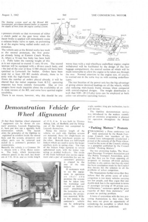
The vehicle seen at the Bristol works last week as the second prototype, the first protope already being at Eastern Coach Works, :d., where a 54-seat bus body has been built t it. Fully laden the running weight of this is is not expected to exceed 11 tons 10 cwt. The second -ototype will be equipped with a 48-seat coach body, and /the end of the year at least 12 RE chassis will have been spatched to Lowestoft for bodies. Orders have been aced for at least 100 RE models already, these to be ainly with the high-frame layout.
From the number of orders placed already, it will be ithered that the initial response from B.T.C. operating )mpanies has been entirely favourable. One or two anagers have made inquiries about the availability of an ft.-wide version of the RE, and some have queried engine There is no reason, however, why this should be any worse than with a mid-wheelbase underfloor engine; engine withdrawal will be facilitated by the design of the rear luggage compartment, the central section of which will be made removable to allow the engine to be taken out through the rear. Normal attention to the engine can, of course, be carried out in the same way as with existing underfloor types.
The rear location of the power unit has the big advantage of giving almost identical loadings on all the wheels, whilst also reducing mid-chassis frame stresses when compared with central-engined designs. The weight distribution is such that 9.00-20 (12-ply) tyres can be employed at both axles—an attractive operating feature.