


A Safety Cut-off for Hydraulic Pipe-lines
Page 36
If you've noticed an error in this article please click here to report it so we can fix it.
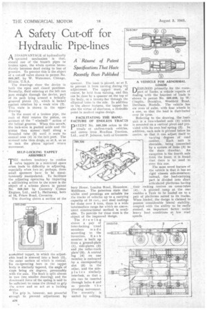
A DISADVANTAGE of hydraulically operated mechanism is that, should. one of the branch pipes be broken open, the *bole system immediately becomes dead owing to loss of pressure. To prevent this is the object of a cut-off valve shown in patent No. 569,367, by W. Waterman, Chicago, Illinois, U.S.A.
The drawings show the device in both the open and closed positions. Normally, fluid entering at the left can pass straight through the device, part of its path lying around a helically grooved piston (1), which is locked against rotation by a weak wire (2). This state is shown in the upper drawing.
In the event of a broken pipe, the rush of fluid rotates the piston, on account of the " windmill " action of the helical grooves. When this occuN, the lock-wire is pushed aside and the piston then screws-itself along a threaded tube (3) until it seats its conical nose (4) in the exit port. The screwed tube then drops, as at 5, so as to lock the piston against return movement.
SELF-LOCKING TAPPET ASSEMBLY "THE modern tendency to confine valve tappets in a restricted space often leads" to difficidty in adjusting, especially when two Or, perhaps, three small spanners have to be simultaneously manipulated. To facilitate the adjusting operation by imparting a self-locking action to the screw is the object of a scheme shown in patent No. 569,240 by Coventry Climax Engines, Ltd., and L. Hathaway, both of 16, Friars Road, Coventry.
The drawing shows a section of the
assembled tappet, in which the adjustable head is screwed into a bush (1), the outer surface of which is conical. Its co-Operating bore in the tappet body is similarly tapered, the angle of sIope being six degrees. presumably with the axis. The bush is split almost in two (see smaller drawirig) and the downward force of the spring is said to be sufficient to cause the thread to grip the. screw and so act as a locking device.
The grip is, however, not powerful enough to prevent adjustment by
sr. spanner. The .oush is pinned, as at 2, to prevent it from turning during the adjustment. The tappet must, Of course, be held from turning, and this can be done by a spanner on the top of the body, or a tommy-bar through the elliptical holes in the side. In addition to the, above features, the tappet has also the virtue of shortness, a desirable
point in modern engine design.
FACILITATING THE MANUFACTURE OF ENDLESS TRACXS PATENT No. 569,336 refers to the treads of endless-track vehicles, and comes from Roadless Traction, Ltd., and P. Johnson, both of Gunners
bury House, London Road, Hounslow, Middlesex. The patentees state that whilst steel pressings are suitable for the tracks of vehicles up to a carrying capacity of 10 cwt., and steel castings for those over 5 tons, there is a wide intermediate range for which no convenient constructional method is available. To prOvide for these sizes is the object of the improved design.
The drawing shows a pair of inter-locking 'tread members made according to the
invention. E a c Ii member is built up from a ground-plate (1), side-plates (2) and the roller-track plate\-(3),. A central lug (4) on one member is embraced by a Corresponding slot (5) in the other, and the sidepla tes similarly interlock, so that a pin can be inserted through holes 6 and so provide t h e pivoting movement. The assembly is united by welding. DESIGNED primarily, for the .trans-. port of Tanks, a vehicle capable of dealing with the heaviest of loads is .shown in patent No. 569,038, by W. Chaplin, Brooklyn, Westfield Road, Dereham, Norfolk. The vehicle has six rows of axles, with four wheels in '— a row, so that the load is distributed over 24 tyres.
Referring to the drawing, the basic unit is a two-wheeled axle (1) which is mounted on a vertical pivot and provided with its own leaf spring (2). Ia addition, each axle is pivoted below its centre, so that it can adjust itself to varying degrees of road camber. Each unit is
steerable, being connected by a system of links (3) to the Main drawbar. An exceptIon is the fourth axle from, the front; it is found that there is Ito need to steer this one.
The most novel feature of the vehicle is that it has no rigid chassis side-members; instead, the load-carrying part is divided into short articulated platforms having their rocking centres on cross-tubes (4). A pivoted ramp at the rear enables a Tank to be loaded on to a pair of platforms suited to its tracks. When loaded, the design is claimed to possess considerable lateral stability, coupled with the ability to be easily steered, an important factor under heavy load conditions at low road speeds.