


Epicyclic cum Hydraulic Transmission
Page 58
If you've noticed an error in this article please click here to report it so we can fix it.
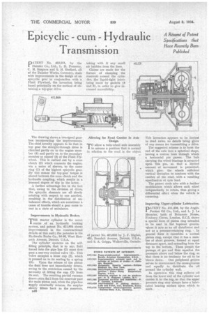
D 4.TENT No. 412,231, by the 1 Daimler Co., Ltd., L. H. Pomeroy, C. M. Simpson and S. H. Shellard, all of the Daimler Works, Coventry, deals with improvements in the design of an epicyclic gear in conjunction with a Fluid Flywheel, the invention being based principally on the method of obtaining a top-gear drive.
The drawing shows a .two-speed gearbox incorporating the improvements. The chief novelty appears to be that in top gear the straight-through drive is clutched partly on to the engine member (4) and partly on to the secondary member or runner (3) of the Fluid Fly-. wheel. This is carried out by a cone clutch (2) which connects the engine, via a series of sleeves, to the outer ring (1) of the highest epicyclic gear. By this means the top-gear torque is shared between the cone clutch and the hydraulic coupling, which results in a lessened degree of slip in the latter.
A further advantage lies in the fact that, owing to the division of drive, the epicyclic elements are all slowly rotating with respect to one another, resulting in the distribution of unbalanced effects, which ,are sometimes a cause of trouble should a gear come to rest in a state of unbalance.
Improvements in Hydraulic Brakes.
THE master cylinder is the nerve centre of an hydraulic braking system, and patent No. 411,864 shows improvements in the constructional details of this unit ; the patentee is the Hydraulic Brake Co., 84-86, West Hancock Avenue, Detroit, U.S.A.
The cylinder• operates on the selffilling principle, that is to say, fluid forced into the pipe line (3) must first pass a one-way conical valve (1). This valve occupies a loose cup (2), which is pressed on to its seating by a spring '(5). Upon the release of the piston the fluid does not immediately return, owing to the restriction caused by the nenessity of lifting the cup (2) from its seat. The resulting partial vacuum draws extra flui I from the reservoir past the main piston and, when the pipe-line Supply eventually returns, the surplus slowly filters back to the reservoir,
B46 taking with it any small air bubbles from the lines.
Claims are made for the feature of clamping the reservoir. around the cylinT der, the liquid-tight joints being made by gaskets (4 and 6), in order to give increased accessibility.
Allowing for goad Camber in Axle Design.
TO allow a twin-wheel axle assembly 1 to assume a position that is normal in relation to the toad is the object of patent No. 411,632 by 3. F. Iiigbee, 481, Beaufait Avenue, Detroit, U.S.A., and S. A. Griggs, Walkerville, Ontario.
This invention appears to be limiteol to dead axles, no details being given of any means for transmittinga drive.
The suggested scheme is to form the end of the axle into a spherical shape, having a central bore through which a horizontal pin passes. The 'hub carrying the wheel bearings is mounted upon this pin, so that a limited amount of movement is permitted,. which give-, the wheels sufficient vertical deviaPon to conform with the camber of the road, with a resulting eqtalizati.m of tyre load.
The patent deals also with a further modification which allows each wheel independently to rotate, thus giving a differential effect when the vehicle is cornering.
Improving Upper-cylinder Lubrication.
DATENT No. 411,426, by the Anglo1 Persian. Oil Co., Ltd., and L. 3. Le IVIesurier; both Of Britannic House, Finsbury Circus, London, E.C.2, shows a special form of piston ring intended to be used in the topmost groove, iiihere it acts as an oil distributor and
not as a pressure-retaining ring. In general form it resembles a normal piston ring, except that it has a number of short grooves, formed at equal distances apart, and extending from the top to the bottom. These permit the passage of gas and thus equalize the pressures above and below the ring, so that there is no tendency for oil to be blown down. One peripheral groove serves to interconnect the cross-grooves and equally to distribute the oil around the cylinder wall.
In operation this ring collects .oil from the lower end of the cylinder and carries it to the top, so that the upper pressure ring may always have a lubricated bearing surface upon which to work.