


An Entirely New and Practical Road Roller
Page 36
Page 37
If you've noticed an error in this article please click here to report it so we can fix it.
IN the past there has been a natural tendency to design internal-combusrion-engined road rollers on lines similar to those of steam rollers; gradually, the details have changed somewhat, but it has nearly always been the practice to place the engine between the members of a deep, platetype frame. Frequently this arrangement gives rise to inaccessibility.
In order to break away from the difficulties in connection wit It " traditional " designs, the Precision oil-engined roller, which has recently been introduced by John Fowler and Co. (Leeds), Ltd., Leeds, has been designed without reference to the use of existing parts.
Each side member of the frame conB24
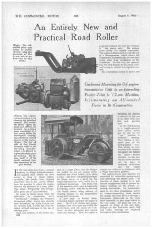
sists of a single plate, and the flanges are welded on, as are certain crossmembers and other details ; I-in. plate is used. The dead axle passing through the frame serves as. a pivot for the engine-transmission unit, which has a cushioned mounting. The front end of the assembly rests upon a transverse leaf spring, and is thus free to rise and fall within limits, being relieved of weaving stresses in the transmision casing and crankcase.
A new type of Fowler threecylindered totally enclosed oil engine is used. The C.A.V.-Bosch fuel pump, fuel pipes and valve gear are within the cover plates, and the intake air is filtered, so that air-borne grit cannot cause any damage. Thus the engine is protected without the need for "boxing
in" the power unit. The various cover plates are rapidly removable. The engine is hand-started with the aid of a decompressor, which allows full compression automatically to come into action after four revolutions of the crankshaft. In this way, the operator can use both hands to the crank without having to attend to a separate control.
The combusion system is direct and turbulent air motion is effected by the use of an offset vane cast into each air-inlet port.
In the bell-housing is a toggle-operated plate clutch, which can be put in the " out " position to
facilitate starting. Next follows a twospeed gear of the sliding-pinion type. This works in conjunction with another two-speed set behind the quick reverse clutches. In this way the size of the clutches can be kept to moderate dimensions and the torque stresses are reduced as coMpared with a single four-speed gearbox.
The quick-reverse cone clutches are controlled by adjustable spring-loaded rods operating the release arms. The function of these springs is to give smooth engagement and to prevent excessive loading on the ,clutch, actuating mechanism. An intermediate shaft in the final transmission carries an internal-expanding brake outside the casing; the final drive is through a four-pinion differential in the finalshaft assembly to gear rings bolted to the rear rolls. All gears are cut, as, opposed to being of the cast type. Except for the final-drive shaft, ball and roller bearings are employed throughout the transmission. The differential may be locked from the footplate and, if required, a cambering axle can be provided at extra cost.
All three rolls are of the steel-plated type, and weights from 7 to 12 tons for the complete roller are obtained without the use of water ballast.
• The front roll is carried in an underslung fork, which is controlled by a hand-operated steering gear of the worm and segment type, with a bevel gear for the angular transmission.
Other controls include a handoperated screw-type brake, which takes effect on the hind rolls, and a hand lever for the clutch. The gear change, for the primary reduction is regulated by a pedal, and the second gear control is hand operated. Extra equipment wliich can be provided includes power steering, watersprayers for the rolls, a power take-off and scarifiers.
This roller, which made its first appearance in November last at the Public Works, Roads and Transport Exhibition, is now fully in production. It is interesting to note that this design has enabled the centre of gravity to be lowered to such an extent that the machine will pass, with full safety, h 40-degree tilting test.
The following are the principal dimensions and performance data of the Precision roller; —Weight, 7 tons to 12 tons; 33 b.h.p at 1,100 r.p.m., giving road speeds of .9 m.p.h., 1.4 m.p.h., 2.8 m.p.h., and 4.3 m.p.h. in either direction; hind rolls, 4ft. Bins. diameter by 20 ins, wide; front roll, 3 ft. 9 ins. diameter, 3 ft. 2 ins, wide; wheelbase, 9 ft. 6 ins.; width of surface rolled, 5 ft. 9 ins.; roll overlap, 41 ins, each side; overall length, 16 ft. 6 ins.; turning circle, 32 ft. 8 ins.