


road and workshop
Page 43
If you've noticed an error in this article please click here to report it so we can fix it.
by Handyman
Benchwise: lathe sense (10)
MANY ITEMS such as trailer leg inner shafts, threaded winding spindles, etc, are damaged quite frequently, and today, I am afraid, the accent is far too much on replacement rather than repair. The trouble is that we are steadily losing the old engineer-type of fitter, and replacing him with the mechanic whose main training has concerned removal and replacement rather than "Mend-it know-how."
I say this with no disrespect to the younger motor mechanic, as it is just a sign of the times, and unfortunately if the new part is not to hand the job waits, with consequent vehicle downtime. So wherever there is a garage lathe do all you can to keep it busy—it will pay you back one hundredfold—not forgetting to look after the lathe steady.
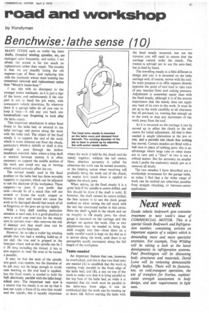
This important attachment is either fixed firmly to the lathe bed, or secured to the lathe carriage and moves along the work with the lathe tool. The object of the fixed steady is to support the end of the work which is some distance out from the chuck, particularly where a spindle or shaft is thin enough to pass through the hollow headstock mandrel. Also, where a long shaft is worked between centres it is often necessary to support the middle portion of the work and avoid any sag or bowing which would seriously affect the cut.
The normal steady used in the fixed position on the lathe bed has three movable supports or registers, which can be adjusted to suit the diameter of the workpiece. These supports—or jaws if you prefer that term—should be of a metal that will not scratch or bruise the work; copper or bronze is ideal and would not cause the work to be damaged should that touch of oil be forgotten, or the jaws set up too tightly.
With a long shaft needing particular attention at each end, it is a good practice to eave a small area over-size for the steady laws to operate over—this removes the risk )1. damage and that small area can be leaned up as the final task.
However, let us take a trailer leg winding ;pindle that has had a welding build-up at me end: the true end is gripped in the hree-jaw chuck and as this spindle can be 2
o 3ft long including the thread, it has to lave support as near the area to be turned a possible.
It may he that the ends of the spindle iave good. true centres, but the diameter of he job may not be large enough to avoid ome bending as the tool load is applied, hus the fixed steady is needed to hold the bait absolutely parallel with the lathe longiudinal axis. The important task now is
o ensure that the steady is so set up that it loes not apply a force of its own that would ,end the spindle; this is equally important where the work iS held by the chuck and the steady together, without the tail centre. Here, absolute accuracy is called for otherwise the work can be turned eccentric, or the bending action when revolving will gradually bring the work out of the chuck, no matter how much force is applied to tighten the chuck jaws.
When setting up the fixed steady it is a great help if the spindle is centre drilled, and this should be done if the shaft is solid. If, however, the shaft cannot be centre drilled, the best system is to use the clock gauge method as when setting the tail stock with the test bar mentioned earlier in this series. Here the shaft is held in the chuck and set up roughly in the steady jaws, the clock gauge is mounted on the carriage and the plunger set against the work. One or two adjustments may be needed to bring the shaft roughly into line—from there on a really careful watch is kept on the dial as it is moved along the work, until there is no perceptible needle movement along the full length of the work piece.
Tests needed
An important feature that can, however, be overlooked, and this is that two final tests are needed (A) to establish that the work is running truly parallel to the front edge of the lathe bed; and (B), a test on top of the work to make sure that it is lying parallel to the top face of the lathe bed, as while it is expected that the work must be parallel to the lathe-way front edge, it can be overlooked that the work can be running up or down hill. Before starting the lathe with
the fixed steady mounted, test out the traverse you will need to ensure that the carriage cannot strike the steady. The trainee is advised not to use the auto-feed, but to feed by hand.
The travelling steady is a little different in design and use: it is mounted on the lathe carriage and, of course, moves with the tool. Its main purpose is to offer support directly opposite the point of tool load to take care of any reaction from tool cutting pressure. Adjustment is somewhat easier than with the fixed steady, although it is of the utmost importance that the steady does not apply any load of its own to the work. It must be set up to the work carefully at nil clearance but nil pre-load, i.e. running fine enough up to the work to stop any movement of the work away from the tool.
As it is mounted on the carriage it can be moved up to either the chuck or the tail centre for initial adjustment. All that is then needed is ample lubrication at the jaw or rest, and a periodic test check that nothing has moved. Certain steadies are fitted with a ball race in place of rubbing jaws: this is an advantage where large tube or other items are to turn and a "thou" or two is not a critical matter. But for accuracy on smaller work I prefer the stationary steady jaw as it removes all doubt.
The two steadies I have described are a worthwhile investment for the garage lathe, as today I find that a far wider range of work can be tackled not otherwise possible from straight chucking, or between-centre application.