


Self-servo Disc Brake
Page 90
If you've noticed an error in this article please click here to report it so we can fix it.
ADISC brake for heavy vehicles is covered by patent No. 809,075. The disc has a brake on its edge which is applied first and the resulting movement is used to work the pads on the sides of
the disc. (Dunlop Rubber Co., Ltd., 1 Albany Street, London, N.W.1„)
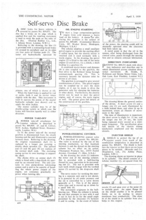
Referring-to the drawing, the disc (1) is provided with a contracting-band brake (2) around its periphery and on its sides are four pairs of friction pads (3). The latter are hydraulically operated by
pistons, one of which is shown at (4).
When the band brake is applied by rod or cable, both it and its carrier rotate slightly with the disc. This movement is used to operate the piston of the master hydraulic cylinder (not shown) and so apply the main brakes.
The master cylinder may be of the double-acting variety in which case the brake Will function equally well in either direction.
POWER TAKE-OFF APOWER take-off attachment for Com-tier vehicles is described in patent No. 809,469. (F. and H. Clifton; 90-91 Arches, Studland Street, Hammersmith, London, W.6.)
To fit the power take-off the normal gearbox is disconnected from the clutch housing and the unit illustrated is inserted between them. Referring to the drawing, the original transmission shaft (I) is replaced by a longer one carrying a double chain sprocket (2). The splined end (3) and the gear (4) are replicas of the normal shaft ends. The enclosing casing carries its own bearings to support the shaft.
The chains drive an output shaft (5) which is fitted with a dog-clutch (6) operated by an external lever. The unit contains its own pump-driven lubricating system and is said to be capable of handling the whole power output, of the engine, yet consumes practically no power when running idle. TO start a large compression-ignition engine from cold imposes a heavy load on the battery. A means tor alleviating this problem is the subject of patent No. 809,405. (Continental Motors Corp., 205 Market Street, IVIuSkegon, Michigan, U.S.A.) The scheme employs a small auxiliary petrol engine to provide the starting effort if called upon, but the electric starter is retained and is used normally with a warm engine. In the drawing, the petrol engine (I) is fitted to the side of the main engine (2) and drives, via a,clutch, a shaft leading to a gearbox (3).
A combined starter-motor and dynamo (4) is also coupled to the gearbox, the final drive to the flywheel being through constant-mesh gearing (5). This is necessary because the dynamo must be driven at all times.
The gearbox is arranged to give several combinations of drive. The petrol engine can be coupled •up to start the main engine, or it can be made to drive the generator only for charging the batteries or other duties. Furthermore, the electric starter can be used to start the petrol engine, and, of course, the main engine as well. The patent gives full details of the construction of the gearbox.
POWER-STEERING CONTROL A POWER-STEERING control valve is described in patent No. 809,301. The valve is worked by the nut of the steering mechanism, so that backlash between it and the thread on the steering column has no effect on its action. (Thompson Products Inc., 23555 Euclid Avenue, Cleveland 17, Ohio, U.S.A.) In the drawing the circle (1) indicates the lower end of the steering column; this is provided with a hall-bearing thread for easy operation in its surrounding nut (2). The nut is provided with rack teeth which engage with the toothed sector (3) carried by the drop-arm shaft (4).
The servo motor for working the steering is a separate unit and is not shown. It is powered by oil under pressure and the oil is controlled by a valve shown generally at 5. This is of the pistonvalve type and is moved up or down by a small link (6).
The movement originates in the ballbearing nut. When the column is turned, the nitt first attempts to turn with it and it can in fact do so for the small angle permitted by the clearance (7) between it and its casing. In the event of failure of the power, the 'steering could still be Manually operated once the clearance
had been taken up, .
A novel point is that the oil in the system, after being discharged from the control valve, passes through the steering box and so ensures constant lubrication.
DIRECTION INDICATORS DATENT No. 809,331 deals with direc
tion indicators and describes one in which illuminated arrows simulate directional movement. (R. Dodds, E. Robinson and Simms Motor Units, Ltd., Oak Lane, East Finchley, London N.2.)
The drawing shows the general outline of the device. A short arrow (1) and a longer one (2) are each illuminated by a bulb behind them, and when lit up in succession, create an illusion of movement to the right.
The time of illumination is important; the short arrow is alight for .12 sec. and the longer one for .55 sec., the cycle being repeated every second as a minimum frequency. The specification gives full details of the electric timing mechanism employed and • the various circuits.
INJECTOR SHIELD A SHIELD to protect the tip of an 1-1 injector nozzle from much of the eombustion temperature is described in patent No. 809,053. The shield is built into the injector so that there are no loose pieces to be mislaid, (Ricardo and Co. (Engineers), Ltd., 27a Ashley Place, London, S.W.1.)
The drawing shows an injector in place in its cylinder. The shield consists of a tubular member (1), air-spaced from the nozzle (2) and spun over at the point (3) to exclude gases. An upper flange (4) on the shield enables it to be pressed firmly on to its seating to ensure maximum heat conductivity. The close fit of the shield in its cylinder bore also helps in this respect.