


Balancing Wheels Electronically
Page 43
Page 44
If you've noticed an error in this article please click here to report it so we can fix it.
By P. G. Tucker
An Ingenious System Which Records Out-of-balance Area and Weight Required for Correction
WH1LST it might be difficult to assess the degree of wear to which tyres, king-pins and wheel bearings are subjected as a result of running with the wheel assemblies out of balance, it is not hard to appreciate that when the out-of-balance forces are great, the continuous pounding on the wheel assemblies can only have a harmful effect.
There is, too, the question of vehicle stability. A vehicle of which I have knowledge was completely unmanageable at 50 m.p.h. After other investigations had been made, the wheels were checked for balance and it was found that a front assembly was out of balance to such a degree that weights totalling 48 oz. had to be attached to the rim. Thereafter there was no difficulty in maintaining perfect control at 50 m.p.h.
Although this is admittedly an exceptional case, it is probably true to say that the vast majority of wheel assemblies on commercial vehicles is out of balance to some degree. Equipment in which the wheel, complete with its tyre, is subjected to a balancing test after removal from the vehicle, has been in use for some time, but no apparatus has been available for testing wheel assemblies for balance by electronic means with the wheels in position on the vehicle.
V. L. Churchill and Co., Ltd., Walnut Tree Walk, Lambeth North, London, S.E.I1, has for a long time been investigating wheel-balancing problems and the outcome is the production of an electronic machine which is claimed to be the first and only British equipment of its type. It is only recently, however, that attention has been devoted to commercial vehicles and the results obtained with the machine prove that exploration in this field is amply justified.
With wheels mounted on a vertical pin, such as those on the front of a vehicle, it is necessary to test for outof-balance forces in both vertical and horizontal planes. This the Churchill machine is designed to do.
The balancer consists of four main units-a spinner motor and contactor starter, a pick-up, an amplifier and a meter and switch panel. The purpose of the spinner motor, which runs off the mains supply and is protected from overload by the contactor starter, is to rotate the wheel assembly being balanced to speeds up to the equivalent of 60 m.p.h., or, in the case of private cars, 100 m.p.h.
The Pick-up
By means of the pick-up which connects with the suspension through a magnet, a wave form is generated and passed to the amplifier, which smooths and peaks the wave form to obtain a precise firing point for the flasher tube. It also measures the height of the wave form and feeds the height, or amplitude, to the meter. A still further operation is to count the flashes of the tube, which are passed to the meter, in the form of revolutions per minute.
The purpose of the meter when the control switch is set to " balance" is to indicate the amplitude of the wave form picked up, and when set to r.p.m. to record the revolutions of the wheel.
A wheel which is out, of balance when it is revolved at speed causes the suspeqsion system to vibrate. The greater the degree of out-of-balance, the more the vibration. This is explained by the fact that the wheel is attempting to rotate about its centre of gravity, whilst the suspension is trying to keep the wheel rotating about its bearing.
The wheel overcomes the resistance of the suspension and the revolving assembly rotates about the centre of gravity for what is known as the resonance period. Vibration is at its maximum when the movement of the wheel and the suspension is Jet harmony. This is known as amplitude. The purpose of the pick-up and the meter is to measure and record the amplitude at resonance. Therefore, the meter reading responds accurately as the wheel slows down and various resonant periods are passed.
To measure vibration in a vertical plane, or the kinetic vibration, the pickup is fitted vertically, that is, its magnet is connected to the underside of the. axle beam. Both upward and downward vibration will cause the peaks to be generated at 180 degrees from each other. For the purpose of balancing, the downward wave is used and the upward wave is led to earth.
Thus, when the tube in the amplifier flashes, the out-of-balance area of the assembly is at 6 o'clock. Before speeding up the wheel, a length of adhesive tape is attached radially to it to act as a reference mark. As the amplifier flashes once every revolution of the wheel, the stroboscopic effect is to make the marker appear stationary in a definite clock position during the resonance period. Therefore, no matter whore the reference mark is applied, the
out-of-balance area will be at 6 o'clock relative to the clock position of, the reference mark noted at resonance. So the balancing weight is affixed to the wheel rim in a position agreeing to 12 o'clock.
As the degree of outof-balance influences the amplitude of the wave form recorded on the meter at resonance, and as the degrees of amplitude can be read from the meter in weight values, it is easy to select the right weight to correct the outof-balance which exists.
To measure dynamic vibration, the pick-up is placed horizontally, the only difference in the balancing procedure being that the firing position is changed 90 degrees. This is due to the position taken up by the pick-up which is connected with its arm horizontal, that is, the magnet contacts with the brake backing plate.
In this position, the vibrations being measured represent the actual movement about the king-pin in a horizontal plane. Therefore, any balancing weight that is found necessary is. in this case, affixed 90 degrees from the 12 o'clock position.
In order that any weight which may have to be added may not affect the kinetic balance, two equal and opposite weights are applied, one to the inside front of the rim and the other to the outside rear.
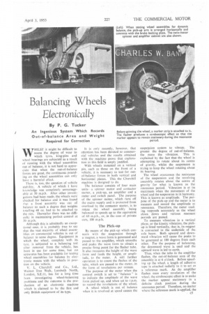
In an actual wheel-balancing operation which I witnessed, the vehicle chosen was a Leyland Tiger coach, operated by Charles W. Banfield, Ltd., Cooper's Road, Old Kent Road, London, S.E.1. The spinner motor, which is comprised of two motors mounted in line, speeded the wheel assembly to an equivalent of 60 m.p.h. On the kinetic test it was found that a I6-oz. weight was required and to obtain correct dynamic balance two 4-oz. weights were necessary.
When the wheel assembly was in a correct state of balance, 'or as nearly so as it was possible to achieve, there was, of course, an absence of vibration. As the pick-up had nothing to record, no wave form was generated and the meter therefore indicated that the wheel was in a state of balance.
In balancing rear wheels the vehicle engine is used to speed up the wheel being balanzed, the wheel that is not receiving attention being held against rotation. It is necessary to take only kinetic balance readings as dynamic vibration is prevented by the solid form of mounting.
The balance weights, of which there are types to fit various wheel rims, are attached in a few seconds by means of a special hammer. '