THE PROBLEM OF WHEEL WOBBLE.
Page 62

Page 63

If you've noticed an error in this article please click here to report it so we can fix it.
T"Eproblem of Wheel wobble, its causes and the methods by which it may be prevented were discussed,' as we have already mentioned, at the meeting of the Institution of Automobile Engineers during the reading of a paper by Dr. F. W. Lanchester on "Automobile Steeringgear Problems and .Mechanism." Although the causes and remedies of wheel wobble and " shimmy " formed the main feature of the paper, there are many points in regard to this subject that were not .touched upon.
It is true that wheel wobble has not reached a point in commercial vehicles where it is calling for drastic measures, but, with the fast coaches now running and with the introduction of low-pressure tyres, one is beginning to bear complaints of this dangerous defect in steering gears. , If the coach of the future is doing to be troubled with wheel wobble it would be as well to have the cause investigated at the earliest moment, so that vehicles that are to be built in later days shall have the benefit of such investigations.
The main point raisedihy Dr. Lanchester took the form of a remedy which he has devised in his hydraulic damping device, but as it is known that some vehicles are more subject to wheel wobble and " shimmy " than others, would it not be wise to correct the form of construction after the suggested investigation of the cause of the defect, rather than add some contrivance which may cure a preventable
• evil*?
Research Necessary to 'Elucidate Causes.
During the discussion which followed the paper various speakers (men of unquestionable experience) gave their views as to the causes of the trouble, and it was evident from the varied character of their views that the reasons for wobble and " shimmy " are not fully understood and that research work of a thorough kind is wanted if accurate .knowledge is to be obtained:
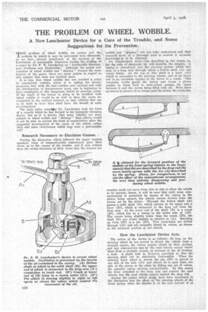
Dr. Lanchester's device was described in two forms, so, for the sake of dearnesS, we will deScribe the simpler. A' casing is introduced into the steering system which consists of a long boss through which a hollow shaft (A) can rotate freely. At the top of this shaft is a lever (Al) which is connected to the steerieg wheels, and at its lower end is an extension similar tO the throw of a crank. This extension works ipside-. the casing and forms a piston similar to those used hi semi-rotary pumps, the space between it and the casing being filled with oil. Were there , no means to permit oil to escape past the piston the crank-like member could not move from side to side to allow the wheels to he steered ; hence, it will be seen that until some communication is permitted by means of the valves in the piston being opened, the wheels cannot deviate from the course set by the driver. Through the hollow shaft (A) passes a solid shaft (B), which carries at its upper end a lever (B1), which is connected to the drag rod from the drop arm. At the lower end of the shaft (13) is a crank (B2), which lies in a recess in the under side of (AS). The recess being slightly wider than the crank (132), the shaft (B) can rotate slightly in relation to (A). Standing. up from (132) is a pin (133). Two cross-holes are drilled through (A2) and are normally closed by valves, as shown in the sectional portion of our sketch.
How the Lanchester Device Acts.
The action of the device is as follows: So long as the steering wheel be not moved to divert the vehicle from a straight course, the valves remain closed by their springs, and any obstructions met by the road wheels cannot divert. them from a straight course, on account of the oil forming a lock. A slight leak is, however, provided so that the steering shall not be absolutely irreversible. When the stOering hand wheel is moved the pin (B3) is moved to one side of the hole (Al) and allows oil to pass from one side of the piston to the other by lifting one set of valves, the opposite valves opening automatically. By this means the lever attached to the drag arm can control the road wheels, but the road wheels cannot control the drag rod.
Among the points which miglit have been mentioned in the discussion was the effect on the steering wheels of the front spring when the shackle is at the rear instead of at the front, as mentioned in an article in the issue of The Commercial Motor for November 22nd, in which it was pointed out that the arc described by the drag rod can be made partially to coincide with that of the spring in one instance, whilst it is directly opposed to it in the other instance. It would seem that the rise and fall of the body on uneven ground may start wobble or " shimmy " in this Manner.
If we are to look for the cause of the trouble we must leave no stone unturned, so it may be well to consider the effect that splayed steering wheels may have on the subject. It is well known that if a wheel that is bowled along be made.to lean over to one side it will, if not otherwise Controlled, describe a circular path as if it were part of a cone.Now, it is evident that two splayed wheels are each trying
to describe circular paths and are only prevented from doing so by the rod which couples them together. Is it not conceivable that any roiling action of the sprung frame may reduce the adhesion of one wheel temporarily and so allow the other wheel to start on a circular course, which would be instantly checked by a roll of the body in the reverse direction, with the same result to the other wheel?
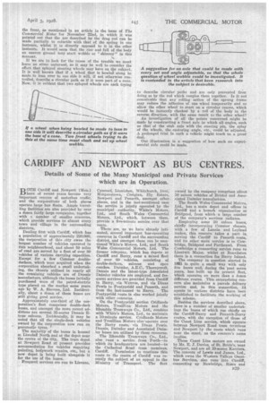
An investigation of all the points concerned might be made by constructing a front axle in which all-angles, such as that of the stub axle with the steering pin, the splay of the wheels, the eastoring angle, etc., could be adjusted. A prolonged trial in such a vehicle might teach us a great deal.
Our illustration is a suggestion of bow such an experimental axle could be made.


