


A NEW MANN BOILER.
Page 32
If you've noticed an error in this article please click here to report it so we can fix it.
A Résumé of Recently Published Patents.
QOME INTERESTINGdevelopments In connection with
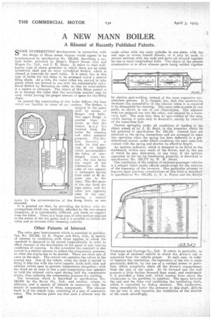
the design of Mann steam wagons would appear to be foreshadowed by specification No. 193,316, describing a vertical boiler, patented by Mann's Patent Steam Cart and Wagon Co., Ltd., and J. H. Mann. It refers to that wellknown type of steam generator in which there are an outer cylindrical shell and an inner cylindrical firebox, which is crossed at intervals by small tubes. It is usual, too, in this type of boiler for the tubes to be arranged round a central firing chute. As a rule, the water tubes are carried in tube plates which are formed in one„ with the substantially cylindrical firebox by flattening its sides, so that its cross-section is a square or rectangle. The object of this Mann patent is so to arrange the tubes that the maximum number may be used, whilst leaving the proper amount of space for the firing chute.
In general the construction of this boiler follows the lines which are familiar to many of our readers.: The firebox i6 secured to the outer shell by means et flanges and bolt.. The upper flange is smaller than the lower, so that the firebox may be lowered from the boiler for cleaning arid other essential purposes. The firebox, however, is made, for that poi-tion of its length which accommodates the tubes, of star shaped cross section, the star being the result of the intersection of the sides of two squares or rectangles having their sides at 45 degrees One to -the other. The flat parts of the star form the tube plates, and the tubes join opposing sides of the star, leaving a central space for the accommodation of the firing chute, as was required.
it is pointed out that, by providing the firebox with the corrugations which are, naturally, afforded by the star-shaped formation, it is considerably stiffened, and needs no support from the tubes.. There is a large area of tube surface exposed to the action of the hot gases, -and it is possible to incline the tubes and so increase their stearning capacity.
Other Patents of Interest.
The valve gear improvement which is patented in specification No. 193,266, by D. Napier and Sons, Ltd., is mainly of interest in connection ,with those engines in which the camshaft is designed to be moved longitudinally in ordei• to effect changes in the distribution of the gases to suit varying conditions of running. In this invention the camshaft is also moved in a similar manner to reduce the compression pressure, as when the engine has to be started. There are three sets of cams on the shaft. The central one operates the valves in the normal way. One of the others, when the shaft is moved to bring it into line wifh the valve tappets, holds both inlet and exhaust valves open to prevent compression altogether ; with the third set of cams in line a part-compression cam operates to hold the exhaust valve open during half the compression stroke, thus reducing the compression pressure for starting.
The invention which is described in specification No. 193,295 by the Rover Co., Ltd., and another, relates to silencers, and is mainly of interest in connection with the details' of manufacture of those components. The silencer itself is of the simple type, consisting of a pair of concentric tubes. The inventors point out that such a silencer may be B48 made either ivith the outer cylinder in one piece, with the end caps or covers brazed thereto, or it may be made in several sections with the ends and parts all secured together by one or more longitudinal bolts. The object of the present construction is to allow silencer parts being welded together
by electric spot-welding, instead of the more expensive oxy acetylene process. It is claimed, too, that this construction increases the accessibility of the silencer when it is required to be dismantled for cleaning. The outer tube is made in two parts, as shown in one of our illustrations. The adjacent ends are spigoted one into the other, and secured by a transverse bolt. The ends may then be spot-welded to the case, whilst leaving it quite easy to dismantle, merely by removal of the transverse bolt.
Correct springing under all conditions of loading is tho object aimed at by J. H. Stott, in the invention which he has patented in specification No. 193,161. Control bars are attached to the spring connections and are arranged to come into operation when the spring has been deflected to a predetermined extent, under which conditions the bars come into contact with the spring and shorten its effective length.
An ignition indicator, which is designed to be fitted to the dashboard, within easy reach of the driver, and by the use of which he may determine, at any time, if the ignition apparatus on his car be functioning properly, is described in specification No. 193,177 by W. H. Shute. The ventilation of the interior of enclosed passenger vehicles is a subject which surely affords ample scope for the exercise of the ingenuity of the inventor. One particular attempt to improve upon previous constructions of this kind is described in specification No. 193,342, by B. A. Payne and the Bristol Tramways and Carriage Co., Ltd. It refers, in particular, to that type of enclosed vehicle in which the driver's cab is separated from the vehicle proper. In such case, in order to improve the ventilation, the separation of the two is made practically definite, by the use of a vertical screen or partition, which completely shuts off the driver's compartment from the rest of the coach. At its forward end the roof projects a little farther forward than usual, and underneath it is provided a false roof, which reaches from above the windscreen to the partition in •question. The space between the real and the false roof constitutes the ventilating shaft, which is controlled by sliding shutters. The windscreen, being immediately below the entrance to this shaft, deflects the air into it., and improves the ventilation of the interior of the coach accordingly.