


A Single-plunger Injection Pump
Page 52
If you've noticed an error in this article please click here to report it so we can fix it.
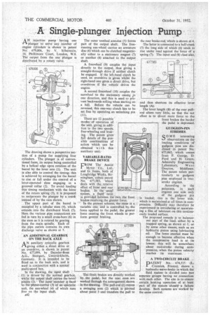
ANinjection pump • having one plunger to servo any 'number of engine cylinders is shown in patent No. 679,006, by V. Silberstein, 14, Phillimore Court, London, W.8. The" output from the one plunger is distributed by a rotary valve.
The drawing shows a perspective section of a pump for supplying four cylinders. The plunger is of conventional form, its output being controlled by a helical edge upon rotation of the barrel by the lever arm (1). The unit is also able to control the timing; this is achieved by arranging for the barrel to rise or fall under the control of. a lever-operated shoe engaging in a grooved collar (2). To avoid loading this timing mechanism with the force of the return spring (3), it is proposed to reciprocate the plunger by a crank instead of by'the cam shown.
The upper part of the barrel is occupied by a tubular stem (4), which extends into the distributor block (5). Here the various pipe connections are fed in turn by a small cross-bore (6) in the stem as it is rotated by gearing from the main spindle. Each of the pipe outlets contains its own discharge valve as shown at 7.
AN ADDITIONAL GEARBOX ON THE BACK AXLE
AN auxiliary epicyclic gearbox giving either a direct drive or an overdrive, is shown in patent No. 677,099, by Daimler-Benz A.G., Stuttgart, Untertikkheim, Germany. It is intended to be fitted on to the back axle, and is used in conjunction with a normal multi-speed box.
In the drawing, the input shaft (1) is driven by the normal gearbox, Whilst flit output Shaft carries the bevel pinion (2). The ihptit .ntembet is fixed to the plariet-carritr (3) of an-epicyclic Unit, the sun-wheel (4) of which runs free on the input shaft.
A42 The outer toothed annulus (5) forms part of the output shaft. The freerunning sun-wheel carries an armature disc (6) Which can be clutched magnetically either to a stationary magnet (7) or another (8) attached to the output shaft.
A freewheel (9) couples the input directly to the output, thus giving a straight-through drive if neither clutch be engaged. If the left-hand clutch be used, an overdrive is given whilst the right-hand one gives a direct drive, but overdrives if the vehicle drives the engine.
A second freewheel (10) couples the sunwheel to the stationary casing fin one direction, and this is used to prevent backwards rolling when starting on a hill. Before the vehicle can be reversed, this one-way clutch has to be set free by operating an unlocking pin (11).
There are 12 possible modes of •operation of , the unit, giving in addition to the two speeds, free-wheeling and brak ing. The patent gives full details of the pos sible combinations of action which can be obtained with this auxiliary unit.
VARIABLE-RATIO BRAKE DEVICE
FROM The Austin Motor ' Co., Ltd., and G. Jones, both of Longbridge Works, Birmingham, comes patent No. 677,583, -which deals with the_ relative effect of front and rear brakes: In the usual system, a fixed' ratio is provided between the two, the front brakes-receiving the greater force. In the present scheme, the ratio is a variable one, and is controlled. by -the
force applied to the pedal, the greater force causing the front wheels to perform greater braking.
The front brakes are directly worked by.. the pedal, but the rear ones are worked through the arrangement shown in the thawing. The pull-rod (1) moves a swinging arm (2) which is pivoted about point 3 and transfers the pull to the rear brake-rod, which is shown at 4.
The latter is connected to a belt-crank. (5) the long side of which (6) tends to rise under load against the force of a spring (7). The input end (8) rises also,
and thus shortens length (A).
. The lever length (B) of filo rear pullrod alters very little, so that the net effect is to divert more force to the, front brakes the harder the pedal is depressed.
GUDGEON-PIN STRESSES
SOME interesting observations on the loading conditions of gudgeon pins are disclosed in patent No. 675,862, which comes from F. George, D. Ford and H. Green, Admiralty Engineering
Laboratory, West Drayton, Middlesex. The patent refers particularly to gudgeon pies employed in twostroke engines.
According to the patentees, in such engines one side only of the gudgeon pin is loaded; this is the lower side, which is maintained at all times in compression. Difficulty may therefore be experienced in introducing or maintaining a film of lubricant on this continuously loaded surface.
The proposed remedy is to balanceout part of the load, either by a trapped spring, as shown at 1, or by some other means, such as an hydraulic piston using lubricating oil. The force exerted must be enough to become effective when the compressive load is at its lowest; this will be somewhere about mid-stroke during compression, when the piston velocity reaches its maximum, A TWO-CIRCUIT BRAKE • DATENT No. 674,515 (L.: J.Coalalert, France), shows a hydraulic servo-brake in which the fluid system is divided _into two separate groups having no' connection with each other. The aim is to ensure certain, braking operation of at least part Of the system 'should —a failure develop. Both systems are worked by the same control.