


Non-sticking Feed V. - Ives
Page 36
If you've noticed an error in this article please click here to report it so we can fix it.
for Hydraulic Brakes
A Resumi of Patent Specifications that Have Recently Been Published , A'hydraulic braking system must of necessity have a one-way valve in the layout for admitting liquid to replace losses, and this valve is liable to stick owing to its infrequent use. To obviate this defect is the object of an improved valve shown in patent No. 539,095 by P. Scott-Iversen and the Rover en., Ltd., Ches-ford Grange, Kenilworth, Warwickshire.
The object is achieved by causing the valve to be forcibly unseated at the end of each working stroke. Furthermore the valve itself is used as a stop • for limiting the piston stroke. An accompanying drawtng shows the master cylinder and the replenishing valve (1). The latter is spring loaded and normally seats on the upper face to act in a one-way direction: When the piston recedes after . use, it strikes a tail-piece (2) on the valve and opens it by tilting as depicted. The use of the valve as an end-stop ensures its opening at the correct place at all times. 5 39 /06 SEPARATE ENGINES FOR BACK AND FRONT DRIVES
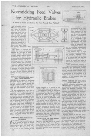
BEARING the name N. Straussler,13yron House, St. James's Street, London, S.W.], comes patent No. 539,097, dealing with a clual-engined vehicle having one engine to drive the back axle and another for. the front axle. --
In the accompanying plan view is 'shown the off-side 'engine (1) which is connected to a central gearbox (2) from which it drives the front axle via a propeller shaft in a torque tube (5). The near-side engine (6) similarly transmits its drive to the gearbox (2) thence via the propeller shaft (3) to the rear
axle. Each drive is indettendent of the other, and could presumablybe used alone if tire loading justified it.
Other features of the patent are the use of a pair of semi-elliptic springs (4) at the rear, in combination with a single transverse spring (7) at the front, thus giving a three-point suspension. The front spring may be V shaped in plan. • COMPOSITE RING FOR PISTON OR SLEEVE
A. SEALING ring intended to act as an oil scraper is shown in patent No. 539,038, by F. Halford and D. Napier and Son, Ltd., 211, Acton Vale, London, W.3. The ring may be used on a piston; or may function in an
inverse manner in a groove in the cylinder wall to seal a sleeve valve. The assembly is built up out of an outer rubbing ring (4) having a bevelled inner face upon which a second ring (5) is pressed by a sEing ring 16) and a backing ring (1"). The result is to exert an expansive force against the sides of the groove.
To prevent wear in the grooves, the composite ring is housed in a pair of annular washers (2 and 3) which are initially stressed in assembly' so as to maintain pressure on the sides of the groove. All the wear, therefore, occurs on the inner face of these washers, and the ring can be replaced as a unit when necessary. The ring cannot be expanded to pass over a piston, so"that it is necessary that a twa-part separable groove be provided.
VINDICATION OF ONE-WHEEL TRACK-LAYER PATENT No.. 539,106 by 0. Singer and C. Dew, 157, Green Dragon Lane, London, N.21, relates to the track-laying attachments for use with one wheel, aescribed in our issue dated September 19.
A twin-tyred wheel surrounded by six track elements is illustrated. These elements (1) are inter-pivoted at the ends and so form an irregular polygon. The essence of the invention is the use of a "lazy-tongs" connection (2), possibly supplemented by links (4) between opposite -pairs of elements, the arrangement being such as to constrain diametrically Opposite.. elements to remain parallel with one another.
This ensures that as each element approaches the ground— for example, element 1—its angular velocity about the pivot at its leading end (in this case 3) diminishes to zero, so that no energy is wasted, nor wear or noise caused, by impact with the ground.
The specification includes a trigonometrical proof of the claim concerning, the diminishing angular velocity of the descending link and further describes other possible linkcontrolling mechanisms, together with an application of the invention to a vehicle having two wheels in close
tandem. In this instance, there ate. eight track elements.
SIMPLE METHOD OF OBTAINING PILOT INJECTION
AMONG oil-engine authorities, the advantages of injecting a small quantity of fuel in advance of the main charge are generally admitted, but hitherto the complicated methods of obtaining two-spurt injection have probably militated against the practice. A means for achieving this end in a notably simple manner is shown in patent No. 539,116 by Sulzer Freres
S.A., Winterthur, Switzerland. • .
This concern proposes to employ a pair of fuel pipes to each injector, one of which is short, and of small bore, and the other long and of larger inside diameter. Iji action, injection from the small short pipe would occur practically instantaneously, whilst that from the larger and longer pipe would, be delayed slightly on account of the volume of the pipe. .
Relative timing of the two spurts .can be influenced by arranging a constriction in the smaller pipe, whilst the larger is made to dimensions such that the main charge starts at or about top dead centre. When not on full load, one or other of the passages can with advantage be cut out altogether.
By employing this " pre-injection !' scheme, it is claimed, .the Main charge burns, in effect, without ignition lag.