


HINTS ON MAINTENANCE.
Page 32
Page 33
If you've noticed an error in this article please click here to report it so we can fix it.
How to Get the Best Out of a Vehicle, to Secure Reliability and to Avoid Trouble.
CONTRIBUTIONS are invited for this page from fleet managers, drivers, garage foremen, and mechanics, works staff and draughtsmen,
and will be paid for on a generous scale. Every system, make,, and type of commercial motor vehicle will be dealt with, and the matter should be written with .a view to the disclosure of workshop and garage practice in the maintenance of a vehicle—practices
which, whilst they may be quite normal, are peculiar to the particular vehicle and may not be generally known to those responsible for its running. Expedients and suggestions for overcoming roadside and other troubles are covered in the following page, dealing with letters from our driver and mechanic readers. Communications should be addressed to " The Editor, The Commercial Motor, 7-15, Rosebery Avenue, London, E.C.1."
284..—Lubricating Brake-shoe Pins on Thomyeroft.
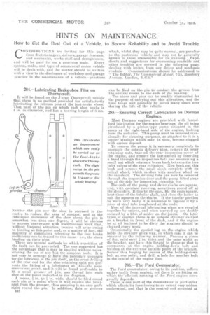
It will be found on the J-type Thornycroft vehicle that there is no method provided for satisfactorily lubricating the fulcrum pins of the foot-brake shoes. That part of the pin on which each shoe works is 1 in, in diameter, and has a bearing length of 3 ins.
Neither the pin nor the shoe is recessed in the centre to reduce the area of contact, and as the rotational movement of the shoe about the pin is somewhat less than one degree, it. will be obvious to anyone conversant with maintenance work that, without frequent attention, trouble will arise owing to binding at this point and, as a matter of fact, the majority of complaints referring to the foot brake inefficiency can be traced to this cause— i.e., the shoes binding on their pins.
There are several methods by which repetition of the fault can be prevented. The one suggested has the advantage that it may be applied without neees• sitaLing the use of any but the simplest tools. It is not easy to arrange tic have the. necessary passages for the lubricant in the pin itself, as the cross-drilling at. the rear end for the shoe-retaining split pin prevents the fitting of a lubricator at this—the most convenient point, and it will be found preferable to fit a small greaser of *-in. gas thread into each shoe at the point indicated in the diagram. A recess, in. to ?1 in. wide, should be filed round each pin ata point where it will receive the lubricant from the greaser, thus ensuring it an easy path right round thepin, In addition, flats or grooves
B4$ can he filed on the pin to conduct the grease from the central recess to the-ends of the bearing.
The shoes and pins can be readily dismantled for the purpose of carrying out. this alteration, and the time taken will probably be saved many times over during the life of the vehicle.
285.—Ensuring Correct Lubrication on Dorman Engines.
Most. Dorman engines 'are provided with forcedfeed lubrication for the engine bearings, the oil being circulated by a pinion-type pump situated in the 'sump at the right-hand side of the engine, looking from the radiator. This pump must be removed occa sionally for cleaning purposes, as attached to it is a 'copper strainer which may, in time, become clogged with carbon deposit. To remove the pump it is necessary completely to uncouple the outside delivery pipe, remove its cover retaining nuts., take off the rear inspection cover of the engine, and remove the last-named by inserting a. hand through the inspection hole and unscrewing a small nut which retains a brass bush between the two inlet valves of the rear cylinders. Now hook out this bush and remove the small shaft complete with its spiral wheel, which meshes with another. wheel on the camshaft. The driving tube can now be removed through the inspection door and the pinup lifted clear out at the side for inspection, cleaning, etc. The ends of the pump and drive shafts are square, and, with constant running, sometimes round off at the shoulders. If this be the case, file the ends square,' heat those of the tubular shaft, and close the latter to suit the squares on the shafts. If the tubular portion be worn very badly it is advisable to replace it by a piece of steel tube toughened at the ends. Most of the internal lubricating pipes are coupled together by unions, and when screwed up are doubly secured by a blob of solder on the joints. On later types of engines there is an outside strainer carried on a bracket in front of the dash, and if the engine be at all inclined to be dirty the strainer should be cleaned every week. Occasionally the special lug on the engine which holds the strainer gives way, in which case it can be
repaired in the following manner. Procure a piece of flat, mild steel in. thick and the same width as the bracket, and have this forged to shape so that it . commences at the engine holding-down bolt and finishes at the extreme outside •point of the bracket. Secure' this forging by means of the holding-down bolt at one point, and drill a hole for, another bolt in the centre of the engine foot.
286.—The Ford Commutator.
The Ford commutator, owing to its position, suffers rather badly from neglect, yet there is no fitting on , which the'effieient running of the Ford engine more greatly depends.
There is One part of the commutator in particular which affects its functioning to an extent very seldom understood, and that is the control rod mounted at
the foot of the steering column, and passing to the arm riveted to the commutator casing. In time the arm and the ball and socket joint to which the control rod is fixed become loose, and movement of the commutator from retard to advance position is upset. It may be as well to describe the normal positions of the commutator for retard, advance, and for easy and safe starting. The fully retarded position on the commutator of the new type Ford engine is where the arm of the commutator stands away from the vertical at approximately 11 o'clock position. Twelve o'clock is the best starting position. If, with the control on the steering wheel at the first notch, the arm of the commutator stands at 11 o'clock position the control is in order, and by advancing it four notches it should reach the 12 o'clock position. With the earlier type, right-hand steering, the commutator arm is mounted at the bottom of the commutator casing, the fully retarded position is 5 o'clock and the starting position is 6 O'clock. Where movement of the ignition control at the head of the steering post does not bring the arm to these positions in-relation to the notch positions already mentioned, it may be necessary to re-rivetthe ball and socket arm, tighten the ball and socket connection, and reset rod connecting control arm to commutator.