


PATENTS SUMMARIZED.
Page 22
If you've noticed an error in this article please click here to report it so we can fix it.
. L.G.O. Gas Equipment. • The lailaton General Omnibus Ca.'s tombined high and low pressuresystem . for the employment of compressed. gas as a fuel for its • vehicles was described in tha columns of this journal ii short time
• ago. The,subject is of .eufficient.impoile • mice, however, to justify cur reproducing on this page the drawings from the patent .specification No. 118,661, which has just been published. It is worthy of note that it is entered in the joint names_ of G. J. Shave and the London General
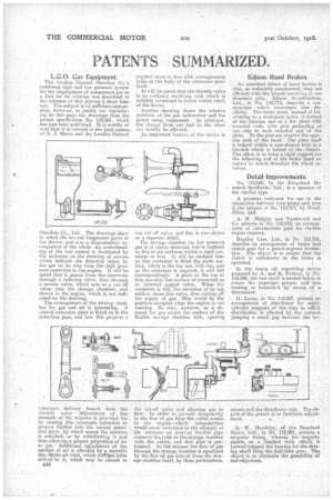
Omnibus Co., Ltd. The drawings 'show in detail the 'several 'component parts of the device, and also a diagrammatic ari•angement of the whole. An understanding of the last named' is facilitated by the inclusion on the drawing of arrows which indicate the direction -taken by the gas on its way. from the high pressure reservoirs to thkengiue. It will be noted that it passes from the. reservoirs through a reducing valve, then through a second valve, which acts as.a cut, off valets, into the, storage chamber, and thence to the engine, which is not indicated on the drawing.
The arrangement of the mixing chainher for gas and air is interesting.. A conical exteusion piece is fitted on to the induction pipe, and into this projects a
telescopic delivery. branch from the thrut le valve. a*djustment of the strength of the mixture is provided for. by causing this telescopic extension to project further into the conical extension piece.. by which ltleaDS the miXture is enriched, or by withdrawing it and thus allowing a greater proportion-of air to gas.: Additional adjustment' of the amount of air is afforded by a Movable disc 6it the air inlet, which disTiaas holesdrilled in it, which may be caused to
1348
register more or less with coriceponoirig holes m the I:Indy-of the extension piece
itself. • It will be noted that the throttle valve is an ordinary revolving cock which is suitably connected to levers within reach of the driver.' , • . Another drawing shows the relative positions of the gas Carburetter and the petrol using component.. :le arranged, the (bailee from one fuel to the other can readily be effected.
An important 'feature of the device is the cue off valve, andthis is also shown as a separate detail.
The storage chamber for low pressure gas is of elastic material, but is confined on five or six surfaces within a rigid container or box. It will he realized that as this container is filled the sixth surface, which is the top one, Will rise, and as the container is emptied, it will fall correspondingly. A plate on the top of this movable feee surface is•connected to an inverted ponet valve. When the container is full, the elevation of its topsurface closes this valve, thus cutting off the supply of ga4, This Would be the poeitiori occupied when the engine is not running. So soon, however, as a• demand for gas occurs the surface of the flexible stoaage chamber falls., opening the cut-off valve and allowing gas to flew. In order to prevent irregularity in the flow ofgas from--the outlet nozzle to the • engine—which' irreplaritiee Weald cause variations in the strength Of the • in ixture—in irteviial.fiszib1e pipe. connects inletto the, sterage. chamber with the outlef, and -this' pipe is per-; furatecl.. Iii' this Manner the flow of gas through the storage chamber is equalized by the flow of gas into or horn the starage chamber itself, by those perforations. Edison Band Brakes. , An admitted defect of baud brakes is that., as ordinarily constructed, they are efficient with the wheels rearelvine iii one direction only. Edson Accurriulatora, Ltd.,in No. 118,773, describe a' con_ struction which overcomes this disa8ility. The brake leer, iustead of f uleruming on a stationery point, is formed at the fulcrum sed-as a flatplatewith rounded ends, With pins projecting at one side at each rourided end of the plate. To the pine are coupled the opposite ends of the band-. Tee plate itself is lodged Within a cam-shaped hole in a • bracket Which is bolted ILO, the
The effect is to form 'a rigid support for the i•ollowihig end of the brake band ne matter in which direetion the whcel revolves.
Detail Improvements.
N.0. 11%556; -by the Kiegalancl Research•Syndicate; Ltd., is a epanner of
the ratchet type. .. •
A piaiseure, indicator • for • nee in the connection hetweee pemp and tyre is the subject of No. 118,717, by WoodMilne, Ltd.
A. -H.Midgley and Vandervell and Co. patent in No. 118,519, an arrangement of intermediate gear for eleelrie engine starters.
Bagitley Cars, Ltd., in No. 118,728, describe an arrangement of brake fend, clutch gear for a petrol-eugined lonelnolive. The object is to ensure that the clutch is withdrawn as the brake is operated.
In the heavy oil vaporizing device patented by A. arid 11. Pulman, in No. 118,506, the fuel itself is heated before it enters the vaporizer proper, and this heating is *controlled by means of a thermostat.
H. Lucas, in No. 118,207, patents an arrangement of distributor or
miIticylinehler magneto of the type in which distribution is effected by the current jumping a small gap between the ter
minais and the distributor arm. The object of Ile patent is to facilitate adjustment.
R. W. Maudsley; of the Standard 141otrLtd., in No. 118,801, patents a magneto fixing, wherein the magneto formed-integral gar albg:iteetarilivi
driving shaft from the half-time gear. The object is to eliminate the possibility of mat alignment.