


For DRIVERS, MECHANICS & FOREMEN.
Page 21
If you've noticed an error in this article please click here to report it so we can fix it.
A PRIZE OF TEN SHILLINGS is awarded each week to the sender of the best letter which we publish on this page ; all-otherz are paid for at the:rate of a penny a line, with-an allowance for photographS. All notes are edited bef,ore being published. Mention your employer's name, in confidence, as evidence of_ good faith. Address, D., M. and P., "The Commercial Motor," 7-15, Rosebery A.Ve_nue, Landon, E.C. I.
Lamps Alight.
On Saturday, 2nd November, light your lamps at 5.1 in London, 5.29 in Edinburgh, 4.5'7 in Newcastle, 5.7 in Liverpool, 5.6 in Birmingham, 5.12 in Bristol, and 5.51 in Dublin.
A Special Type of Valve-cap Spanner.
The sender of the following communication has been awarded the 103. prize this week.
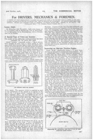
[1912] " A.H.H." (Llandaff) writes Most drivers have trouble atsome time or other owing to 011re caps which have become tight in their threaded holes. Nearly eVeryone knows now that the proper procedure with such components is carefully to line the threads with plunnbago, graphite, or a similar substance when replacing them, ...so that they will be 'more likely to come away freely the next time it is desired to re:Move them. Unfortunately, even when this is done? the trouble sometimes occurs. A great help at any time it a suitably and. well-designed spanner, and the following description is of such a tool
A certain type of commerCial vehicle engine has valve caps which are fitted with vertical.tommy holes
1# in. apart. The spanner which is supplied as part of the equipixient of the chassis is as shown in the sketah No. 1 of those•which I enclose [We have had these redrawn.—En.]. An oval flange at one end is fitted with two steel studs correctly centred so as to fit the toramy holes in the valve cap. The other end is hexagon in shape, l in. across the flats. The whole tool is 9 ins. loneover all, andthe base and head of it are connected by bar about t in. diameter. The tool which I designed is, in my opinion, a considerable improvement on this, and as there are many ef this type of wagon on the road, a description of it will undoubtedly interest several of your readers. It should be noted in the first place that the exhaust valve caps are fitted with screwed plugs, the thread of which is precisely the same Be that on a sparking plug. This has-the effect of rendering the valve ch,ps interchangeable, and no doubt it was with that object that they were so designed. However, I have taken advantage of the fact in making a more efficient span
ner. •
"I procured a piece of hexagon bar 1/ in. on the fiats and about 6 ins. long. I got a blacksmith to jump one end up to g ins, diameter by about .1 in. thick making the tool about 41 ins. long over all, I turned this base up, and trued up the other end of the hexagon, and then drilled, an -Win. hole through, from end to end. Two studs, the right centres to fit the toramy h-oles in the valve caps, were screwed into
the base. A piece of bar was then procured, one
end being screwed and tapped to fit the sparking plug hole, the remainder being reduced to in. diameter and screwed Whiaorth thread at the Opposite end. This bar was slipped inside the -Hein, hole of the spanner, and a nut put on the 'Whitworth end.
"là use, when it is desired to remove a valve cap, first take out the central plugs, screw this inner rod of the spanner into the plug hole, tighten thesspanner itself on to the top of the valve cap by-means of the t-in. Whitworth nut. An ordinary open spanner can now be applied to the _hexagon portion of the tool, and the cap screwed, unscrewed, or otherwise manipulated with ease."
Improving an 014-type Traction Engine. .
[1913] .` G,M." (BakeWell) writes:—" 1 . have been . driving an old-pattern Compound steam tracter. For a considerable time I had frequent recurrence of
trauble. With the back joints of the cylinder, which seemed to be for ever blowfine andsometimes actu ally blowingout the joints. • On investigation it cies curred to me that this ;Must be due to the design of the slide bars. • These are of the cylindrical type, and are bolted direct to the cylinder covers. They are not, -as is usually the case, supported from the boiler. *
After having had several times to take down the whole of the motion gear, in order to renew the jointing be tween cylinders and covers, I decided to try to get at the root of the evil and.designed a support for the slidebars. .I attach a sketch [We have had this redrawn.—En.] Showing the method which I adopted. "A piece of mild-steel bar' was bent to the shape of the boiler barrel. This served as a base. In the centre of it and standing vertically was welded a pillar of 1-in. round steet bar, screwed for a portiOn• of its length from the top end. A cross piece, also of steel bar, 1 in. by in., was made to pass under both slide bars, and was prevented from Moving -with regard to these elide bars by means of a couple of pegs. The cross pieee wan supported in place by a nut on the vertical ,pillar and held firmly by a lock nut above. This support has now been in use for a long time, and has given every satisfaction. Since fitting it I have not, had a recurrence of the trouble with the back cylinder joints.
"I note that on later type tracters made by the same firm as mine is, the slide bars are supported from the boiler and not merely from the cylinder."