


ARE RADIUS RODS NECESSARY?
Page 12
Page 13
If you've noticed an error in this article please click here to report it so we can fix it.
Transmission to the Frame of the Torque and Driving Stresses in Live Axle Vehicles. The Relative Merits of ,Spring Drive and Radius Rods
(From the Designer's Point of View.)
.. HERE ARE MANY points in the design of the petrol-driven motor lorry which are what might be called matters of opinion. That is to say, alternative methods of construction are -met with in similar cases, each Of which is claimed by the particular maker concerned to be the better way of overcoming a given difficulty—or fulfilling. a particular function.
A well-known case in point which has, at one time or another, excited considerable controversy is concerned with the transmission to the frame of the torque and driving stresses in live-axle vehicles.
There are to be found on the market, at the present time, various types of design, some of which utilize separate torque and radius rods for this purpose, e.g., Ma,udslay ; some with a combined torque and radius rod member as the Leyland, and, again, some with neither torque nor radius rod, properly so called, in which both these functions are served by the bear ing springs. .
The writer has been identified with the design of each of these various arrangements at different times, and has, after considerable experience of the performance of the spring-drive arrangement, as it may be called, arrived at the conclusion that, not only are the results satisfactory, but the use of any form of special torque or radius rod member is totally unnecessary, and, in fact, merely results in the addition of useless yeight, cost of construction, and upkeep of wearing parts.
We are, of course, familiar wit' the rather gratnitous assertion often found in criticism in the technical press of a new design incorporating the spring drive, that this type of construction is unsound, seeing that it imposes improper and-excessive loads on the bearing springs which must therefore be prevented from performing their proper function, viz., B32 that of carrying the weight of the vehicle and absorbing road shocks.
This assertion is rarely, if ever, backed up by any form of considered argument, and is delivered in a sort of " ex cathedra" manner, which implies that further argument is unnecessary and, therefore, useless.
Latterly, however, one is pleased to note a tendency on the part of our armchair critics to become less dogmatic in this respect, and in a recent article of the kind referred to, on the subject of a well-known make of vehicle, a remark was added to the general criticism to the effect that, perhaps, after all, the arrangement might work well enough in practice.
Curiously enough, as inferred above, this supposition is quite correct, and the arrangement not Only " might " but doer work well enough to satisfy the most critical, always provided the details are correctly worked out.
Lest, however, the writer himself be accused of this dangerous habit of dogmatizing, it might be well to quote a little chapter and verse, so to speak, and inquire into the mechanical state of affairs pertaining in a design so unorthodox, in which inquiry we shall attenarit to show that matters are not, after all, so bad for the poor overloaded and ill used springs as the casual reader might be led to suppose.
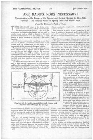
Let us consider a typical 4-ton lorry constructed to take a gross load of 4 tons on the rear axle. Neglecting, for the moment, all consideration of torque and tractive effort, it is clear that, at all times, each rear spring will be called upon to sustain a load of 21 tons, which results in a stress on each spring eye of half this amount or 2520 lb. (see Fig. 1).
If, in addition to this, we propose to transmit both the tractive effort or " push" and the torque reaction through the same springs, the worst ease will obviously occur on the lowest gear when the road wheels are transmitting their maximum power.
Torque, of course, gives rise to the tendency of the rear axle casing to revolve in the opposite direction to that of the road wheels, which tendency must be resisted by a reaction equal and oppeaite to the torque or turning moment. This resistance, in the case we are considering, is afforded by fixing the spring and spring seat rigidly to the axle casing, rotation of the whole then being prevented by the spring pins which transmit the torque reaction to the frame of the vehicle. '
It will be seen, on further consideration, that half of the total turning moment is dealt with by each spring, which half is, in turn, divided between the front and rear supporting pins, the front pin being subjected, in effect, to an increase and the rear One to a decrease of bearing load, as will be seen-by reference to Fig. 1.
In additton to this we have to consider an entirely separate force, viz., that due to the tractive effort or " push " imparted to the vehicle by the engine, which acts horizontally and is transmitted through the front half of the spring only, the rear half, of course, being shackled to allow for flexion and therefore inoperative.
We shall now endeavour to arrive at approximate values for the various forces mentioned, and indulge in a little mild exercise in mechanics, employing the principle of the parallelogram of forces to discover their cumulative effect on the load-carrying capacity of the spring.
Taking a fair average case, we may assume the horse-power of our vehicle to be 40 at 1000 r.p.m., the efficiency at the road wheels, allowing for losses in transmission, being 80 per cent. approximately. Further, let us suppose that the total reduction on low gear between engine and rear axle is 44 to 1 and that the 'road wheels are 41 ins, in diameter.
The wheels, therefore, revolve on low gear at 22.7 r.p.m., and the torque (at the road wheels) may 63.024 X H.P.
be found from the formula : T — to R.P.M.
be approximately 89,000 lb. ins., or 44,500 lb. ins. through each wheel.
Assuming,' now, that our springs are 4 ft. 6 ins. long and the centre of the axle is 10 ins, below the spring pins (see Fig. I), the distance from the centre of axle to each spring pin, approximately 29 ins., represents the radius at which the torque reaction is taken up. The load on the pin due to this will there 44.500 fore be — 770 lb. acting in a direction tangent'al 29 x 2 • to the radius (Fig. 2).
We have now to find the value of the tractive effort transmitted by each wheel, and as the radius is 44.500 20.5 ins, this will obviously be — or 2170 lb.
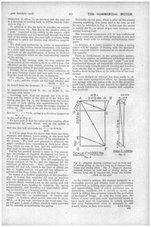
It will be clear from the above that there are three separate and distinct forces acting on the front half of the rear spring at the point of its attachment to the frame. We shall now proceed to discover the single resultant force equivalent to their total effect, from which we can, in turn, find the additional vertical load on the spring caused thereby.
Taking for granted merely a more or less elementary knowledge of Applied Mechanics, we have in Fig. 2 AB representing the tractive effect or "push" of 2170 lb. (compare Fig. 1). Also AD represents the torque reaction of 774 lb.; and the diagonal AC the resultant of these two. Now, considering this resultant AC and AE, which is the load on spring pin due to weight carried, we get AF the ultimate resultant of the three forces AB, AD, and AE By means of a further application of the parallelogram of forces, this resultant AF may be resolved into two components, AG and All, of which AG represents direct vertical load on the spring and All a horizontal force tending to compress the spring longitudinally, and therefore not appreciably affecting its function as a bearing spring. On comparing AG with AE, we see that the actual excess load due to transmission of torque and "push" or tractive effort merely amounts to about. 700 lb., or 28 per cent. increase in the worst case, viz., on low gear, a state of affairs which is easily provided for by suitably proportioning the spring. Naturally, on top gear, which is after all the normal running condition, this extra load is far less, as will be seen by reference to Fig. 3. In this case the excess is merely 250 lb., or about 10 per cent. increase over normal bearing load.
The horizontal component All is not sufficiently great to cause any trouble with spring pin or eye, and is easily dealt with by suitably strengthening these parts.
In iractice, it is easilypossible' to design a spring which will be capable of dealing with the increased loads required without detriment to its shock-absorbing capacity.
There is, furthermore, in the spring-drive system, as the term applies, an additional advantage derived from the fact that the torque and " push " are both transmitted through an essentially resilient member, an obvious help towards smooth running and freedom from shocks due to sudden application of power or brakes, these being taken up by deflection of the road springs.
In some designs an attempt has been made to obtain this same spring-drive effect by incorporating coil springs with the radius rods, or in the propeller shaft itself, although it can scared-3r be claimed that the result justifies the extra expense and complication involved.
In the writer's opinion, this strange antipathy to a thoroughly proved and. reliable form of construction is attributed to nothing more than excessive caution and conservatism, both of which attributes are, in themselves, excellent, but if carried to excess only result in stifling tate progress towards the perfection of mechanical design. As with the worm gear, the failure of some early and crude applications seems to have made such an impression in certain quarters that some fundamental error in principle is still feared, where, in fact, none exists. LrvE A10:11.