


Patents Completed.
Page 20
If you've noticed an error in this article please click here to report it so we can fix it.
A Rear "Stop" Indicator.
E. H. Chagny, No. 9717, dated 24th April, 1912.—A signalling device is fixed on the rear of a motorvan to indicate when speed is to be slackened or the car
stopped. In the construction illustrated, a lamp is made to rotate by means of a link connected with the clutch-operating pedal. When the pedal is depressed, the lamp is turned or some other indication is given. If desired, the device may also be operated by a separate pedal.
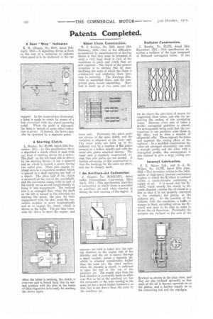
A Starting Clulch.
L. Biehler, No. 20,500, dated 16th September, 1911.—In this specification there is described a clutch which is used with any kind of starting device for a motor. The shaft on the left-hand side is driven by the starting device; it has a squared end on which is located a sleeve having two radial pins. These pins engage inclined slots in a concentric member which is pinned to a shaft carrying one half of a clutch. The other half of the clutch is mounted oil the end of the crankshaft, and the concentric casing with its half of the clutch can be moved longitudinally to bring it into engagement. The inclined slot is so arranged that, when the shaft on the left is turned in the direction for starting the motor, the pins, by their engagement with the slot, cause the concentric member to move longitudinally and so to engage the clutch, which is shown on the right. The pin then transmits the drive to start the engine, and
when the latter is running, the clutch is over-run and is forced back into its normal position with the pins at the heads of their respective slots ready for starting the motor again.
Silent Chain Construction.
W. J. Belcher, No. 3505, dated 12th February, 1912.—One of the difficulties encountered by manufacturers of driving chains is that they must be prepared to carry a very large stock in view of the variations in pitch and width that are now required. The object of the present invention is to obviate this by standardizing the units of which the chain is constructed, and rendering them more
easy to assemble. The drawings illustrate an assembled chain, and the component parts before assembling. Ertei. link is made tip of two outer and on,
inner unit. Preferably the outer units are always of the same width, and the variation is obtained on the inner unit. The outer units are built up in the ordinary way by a number of flat plates secured on a hollow spindle and with the usual side plates attached thereto. The inner unit is similarly constructed, except that side plates are not needed. A further advantage of this construction is, that the bushings for the units are short, and can be cheaply made.
An Auxiliary-Jet Carburetter.
J. Fttgard, No. 26,912/1911, dated under International Convention, 22nd April, 1911.—This specification describes a carburetter in which there is provided an auxiliary jet used when starting or during the slow running of the engine. A separate air inlet is taken into the mixing chamber on the engine side of the throttle, and the air is drawn through a small conduit, across a separate jet, which is situated considerably higher than the main jet; the extra suction. when the throttle is closed, is sufficient to raise the fuel to the top of the auxiliary jet. The supply pipe from the feed chamber is preferably made to allow easy flow as far as the auxiliary jet, but the remainder of the tube leading to the. main jet has a much higher resistanee, so that fuel is not drawn from the main by the auxiliary jet.
Radiator Construction.
C. Bondin, No. 28,276, dated 15th December, 1911.—This specification de. scribes a radiator of the type composed of flattened corrugated tubes. It has or its object the provision of means for supporting these tubes, and also for improving the cooling of the circulating water. Between every pair of tubes a double corrugated partition is placed, the arrangement being such that the corrugations in one partition cross those in the other, and so form a. number of ellipsoidal cells. These support the tubes and augment the cooling effect of the radiator. In a modified construction the tubes are arranged alternately, one with a straight profile and the other with a. corrugated profile, this arrangement is also claimed to give a large cooling surface.
Internal Lubrication.
F. E. Baker, Ltd., and S. J. H. Wilkes, No. 14,792, dated 25th June. 1912.—This invention relates to the lubrication of high-speed internal-combustion engines in which the flywheel is enclosed within a crank-chamber containing a
supply of oil. It is found that the flywheel, which usually fits closely to the crank chamber, carries the oil round in a. film so that it is not properly conveyed to the crankpin, the piston, or the gudgeon pin. At the junction of the cylinder with the crankcase, a baffle or scraper is fixed, extending across the flywheel and close to its edge in order to divert the oil therefrom. Preferably the scrapers are inclined to the axis of the flywheel as shown in the plan view, and they are also inclined upwardly so that some of the oil is thrown upwards on to the piston, and a further supply on to the connecting rod and the crankpin.