


A Floor
Page 66
If you've noticed an error in this article please click here to report it so we can fix it.
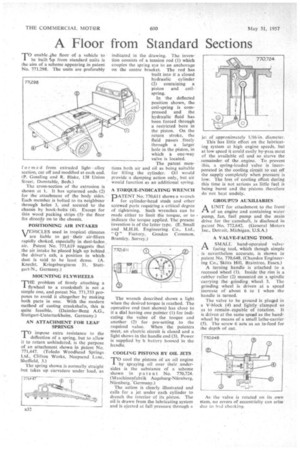
from Standard Sections TO enable ..he floor of a vehicle to be built 4m from standard units is the aim of a scheme appearing in patent No, 771,298. The units are preferably
f or m ed from extruded light alloy section, cut off and modified at each end. (P. Gossling and R. Blake, 138 Union Street, Dunstable, Beds.)
The cross-section of the extrusion is shown at 1. It has upturned ends. (2) for the attachment of the body sides. Each member is bolted to its neighbour through holes 3, and secured to the chassis by hook-bolts (4). Except for thin wood packing strips (5), the floor fits directly on to the chassis.
POSITIONING AIR INTAKES
VEHICLES used in tropical climates are liable to get their air-filters rapidly choked, especially in dust-laden air. Patent No. 771,619 suggests that the air intake be placed high up behind the driver's cab, a position in which dust is said to be least dense. (A. Knecht, Kriegsburgturm 31. Stuttgart-N., Germany.)
MOUNTING FLYWHEELS
THE problem of firmly attaching a flywheel to a crankshaft is not a simple one, and patent No. 771,733 proposes to avoid it altogether by making both parts in one. With the modern method of casting crankshafts, this is quite feasible. (Daimler-Benz A.G., Stuttgart-Unterturkheim, Germany-)
AN ATTACHMENT FOR LEAF SPRINGS
TO impose extra resistance to the deflection of a spring, but to allow it to return unhindered, is the purpose of an attachment shown in patent No, 771,447. (Toledo Woodhead Springs Ltd., Clifton Works, Neepsend Lane, Sheffield, 3.)
The spring shown is normally straight but takes up curvature under load, as indicated in the drawing. The invention consists of a tension rod (1) which couples the spring eye to an anchorage on the centre bracket. The rod has built into it a closed hydraulic cylinder (2) containing a piston and coilspring.
In the deflected position shown, the coil-spring is compressed and the hydraulic fluid has been forced through a restricted bore in the piston. On the return stroke, the fluid passes freely through a larger hole in the piston, in which a one-way valve is located.
The patent mentions both air and oil as being suitable for filling the cylinder. Oil would provide a damping action only, but air would function as an additional spring.
A TORQUE-INDICATING WRENCH
DATENT No. 770,611 shows a wrench
for cylinder-head studs and other screwed parts requiring a critical degree of tightening. Such wrenches can be made either to limit the torque, or to indicate the torque applied. The present invention is of the latter type, (E. Small and M.H.H. Engineering Co., Ltd., " Q " Factory, Gosden Common, Bramley, Surrey.) The wrench described shows a light when the desired torque is reached. The operative end (not shown) has close to it a dial having one pointer (1) for indicating the value of the torque and another (2) for pre-setting to the required value. When the pointers meet, an electric circuit is closed and a light shows in the handle end (3). Power is supplied by at battery housed in the handle.
COOLING PISTONS BY OIL JETS TO cool the pistons of an oil engine by spraying oil over their undersides is the substance of a scheme shown in pat e nt No. 770,724. (Maschinenfabrik Augsburg-Ntirnberg, Nurnberg. 'Germany.) The action is clearly illustrated and calls for a jet under each cylinder to drench the interior of its piston. The oil is drawn from the lubricating system and is ejected at full pressure through a jet of approximately 1/16-in. diameter.
This-has little effect on the lubricating system at high engine speeds, but at low speed it could easily by-pass most of the available oil and so starve the remainder of the engine. To prevent this, a spring-loaded valve is incorporated in the cooling circuit to cut off the supply completely when pressure is low. The loss of cooling effect during this time is not serious as little fuel is being burnt and the •pistons therefore do not heat unduly.
GROUP D AUXILIARIES
A UNIT for attachment to the front
of an engine and containing water pump, fan, fuel pump and the main drive for the camshaft, is disclosed in patent No. 772,642, (General Motors Inc., Detroit, Michigan, U.S.A.) A VALVE-FACING TOOL
ASMALL hand-operated valvefacing tool, which though simple is nevertheless accurate, is shown in patent No. 770,648. (Chandos Engineering Co., Skitts Hill, Braintree, Essex.)
A turning handle is attached to a recessed wheel (1). Inside the rim is a rubber roller (2) mounted on a spindle carrying the grinding Wheel 3. The grinding wheel is driven at a speed increase of about 6 to 1 when the handle is turned.
The valve to be ground is pined in a V-block (4) and lightly clamped so as to remain capable of rotation. It is driven at the same speed as the handwheel by means of a small lathe-carrier (5). The screw 6 acts as an in-feed for the depth of cut. • As the valve is rotated on its own stem, no errors of eccentricity can arise due to Mc! chucking.