


A Simple Automatic Gearbox
Page 66
If you've noticed an error in this article please click here to report it so we can fix it.
A Rsurne of Recently Published Patent Specifications. AGEARBOX in which the ratios are selected by a combination of speed and torque values is disclosed by P. Mattia, 12, Via Passerella„ Milan, raly, in patent No. 427,235. The gear, is of the simple-epicyclic type, which gives two ratios—a reduction and a direct drive. The power shaft (7) is fixed to a disc carrying planetary axles (8). On each of these axles are mounted a drum (1), and two pinions (2) and (3). Pinion 2 meshes with a gear (6), which forms the output member, whilst pinion 3 drives a gear (5), which is permitted only unidirectional movement by a free wheel (4).
In operation, at starting, when the torque is high, the drive passes through the planetary pinions with a consequent reduction in ratio. As the engine speed rises with a falling torque, the drums .,(1), which are internally vaned and filled with mercury, offer an increasing resistance to planetary rotation owing to the centrifugal action of the rotation about the main axis. This resistance increases with speed until it finally brings about a complete stoppage of planetary motion, thus giving a direct drive. In order to obtain more than two ratios, the mechanism may he duplicated, the design illustrated having two similar elements in series.
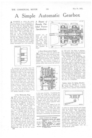
A New Wellworthy Ring.
rtA NEW piston ring design, the object of which is to prevent the gas pressure from reaching the back of the ring and forcing it into heavy contact with the cylinder, is shown in patent No. 427,001 by Wellworthy, Ltd., and J. W. Howlett, both of Radial Works, Lymington, Hants.
The drawing shows two sections of the ring at different points of its periphery. A bevelled edge (2) on the upper face has a number of holes (1) which lead to a groove (4) in the lower face; by this means the pressures on the upper and lower faces are put into equilibrium. In addition, a number of gaps (3) are cut in the lower face; this seems unusual, owing to the fact that a definite gas leak appears to be established via the holes (1), grooves (4), and the gaps (3). The explanation may lie in the recom 648 mended use of three of these rings, the lowest one being made without the gaps (3), the object apparently being to break down the gas pressure in steps.
A Novel Rotary-piston Engine.
ANengine in which the pistons follow a circular path around an annular cylinder is shown in patent No. 427,014 (void) by P. Laszlo and Naxos Schmirgelwarenfabriks A.G., Budafok, Hungary. The cylinder consists of a hollow ring and contains a number of pistons which slide around the cylinder
in the same direction. Considering the action of a single pair of pistons, one of these (5) is fixed with respect to the central main shaft by means of a spider (4). The other piston (2) is fixed to a similar spider (3) which forms one member of an unusual epicyclic train, to be described later.
The action of the engine is as follows: One of the pistons travels at a constant velocity, whilst the other alternately accelerates and slows down, thus forming a varying capacity between them. During the period when this space is increasing, the pistons pass an inlet port, and draw in mixture. The hindmost piston then accelerates and compresses the gas until it is fired when passing a sparking plug.
The mechanism for producing the varying motion of one piston consists of an epicyclic train of curious construction. A gear (7), fixed to the main shaft, drives a layshaft gear (8). On the layshaft is a gear (1) meshing with another (6) mounted on a sleeve carrying the spider of one set of variable-speed pistons. The gear (6) is not circular, however, having 'four pro. nounced nodes on its periphery, whilst its mating gear (1), being half-size, has two corresponding depressions. The action is that through a certain angle the train runs as an increasing gear, and for the following stroke changes the ratio to a reduction.
Rubber Joints for Spring Shackles.
I N patent No. 427,104, V. A. Trier, of Andre Works, Victoria Gardens, London, W.11, discloses improvements in joints for spring shackles and torque rods, at the point where they connect with the frame. The specification describes 14 different embodiments of the invention, one of which we illustrate; In this case, the upper pivot pin (1) passes through a block having two pins (3) which are gripped by compressed rubber bushes held in the frame bracket (2). The chief claim: in the patent is the employment of at least one rubber-bushed joint, the axis of which is at right-angles with the spring-shackle pivot.