


TRACK JOINTS FOR ENDLESS-TRACK VEHICLES.
Page 70
If you've noticed an error in this article please click here to report it so we can fix it.
A Résumé of Recently Published Patent Specifications.
ANEW form of joint for the tracks of vehicles that are intended to travel over ground with soft surfaces, such as is to be found where no roads have been made, is described by the Roadless Traction Co., Ltd., and Oscar Styles Penn, in their specification No.
269,644. It is well known that the joints of such tracks have, in the past, given trouble owing to the difficulty of retaining lubricant and preventing grit from entering the joints.
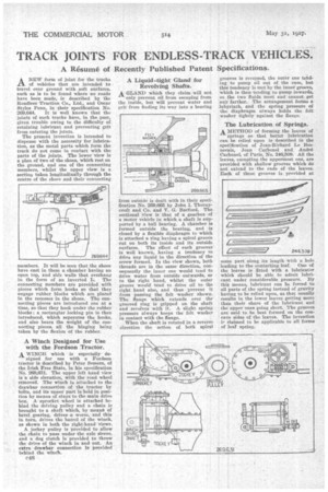
The present invention is intended to dispense with the necessity for lubrication, as the metal parts-which form the track do not come in contact with the parts of the joints. The lower view is a plan of two of the shoes, which rest on the ground, and one of the connecting members' whilst the upper view is a section taken longitudinally through the centre of the shoes and their connecting
members. It will be seen that the shoes have cast in them a chamber having an open top, and side walls that overhang in the form of an inverted L. The connecting members are provided with pieces which form hooks so that they engage rubber blocks which are placed in the recesses in the shoes. The connecting pieces are introduced one at a time, so that they hook under the rubber blocks; a rectanglar locking pin is then introduced, which separates the hooks. and also bears the weight of the connecting pieces, all the hinging being taken by the flexion of the rubber.
A Winch Designed for Use with the Fordson Tractor.
A WINCH which is especially de signed for use with a Fordson tractor is described by Peter Somers, of the Irish Free State, in his specification No. 269,621. The upper left hand view is a side elevation, with the road wheel removed. The winch is attached to the drawbar connection of the tractor by bolts, and its upper part is held in position by means of stays to the main drive box. A sprocket wheel is attached behind the driving pulley and a chain is brought to a shaft which, by meant of bevel gearing, drives a worm, and this in turn, drives the barrel of the winch, as shown in both the right-hand views.
A jockey pulley is provided to allow the chain to pass under-the axle sleeve, and a dog clutch is provided to throw the drive of the winch in and out. An extra drawbar connection is provided behind the winch.
C48
A Liquid-tight Gland for Revolving Shafts.
A GLAND which they claim will not only prevent oil from escaping from the inside, but will prevent water and grit from finding its way into a bearing
from outside is dealt with in their specification No. 269,665 by John I. Thornycroft and Co. and V. G. Barford. The sectional view is that of a gearbox of a motor vehicle in which a shaft is supported by a ball bearing. A chamber is formed outside the bearing, and is closed by a flexible diaphragm to which is attached a ring having a spiral groove cut on both its inside and its outside surfaces. The effect of such grooves is well known, having a tendency 10 drive any liquid in the direction of the screw formed. In the view shown, both threads are in the same direction, consequently the inner ime would tend to drive water from outside outwards, or to the right hand, whilst the outer groove would tend to drive oil to the right hand also, and thus prevent it from passing the felt washer shown. The flange which extends over the grooved ring is gripped on the shaft and revolves with it. A slight spring pressure always keeps the felt washer in contact with the flange.
When the shaft is rotated in a reverse direction the action of both spiral grooves is reversed, the outer one tending to pump oil out of the case, but this tendency is met by the inner groove, which is then tending to pump inwards, so the two fluids meet and cannot get any farther. The arrangement forms a labyrinth, and the spring pressure of the diaphragm always holds the felt washer tightly against the flange.
The Lubrication of Springs.
A METHOD of forming the leaves of
springs so that better lubrication can be relied upon is described in the specification of Jean-Richard Le Besnerais, Jean Carbonel and Andre Carbone!, of Paris, No. 246,509. All the leaves, excepting the uppermost one, are provided with shallow grooves which do not extend to the ends of the leaves. Each of these grooves is provided at some part along its length with a hole leading to the contacting leaf. One of the leaves is fitted with a lubricator which should be able to admit lubricant under considerable pressure. By this means, lubricant can be forced to all parts of the spring instead of gravity having to be relied upon, as that usually results in the lower leaves getting more than their share of the lubricant and the upper ones going short. The grooves are said to be best formed on the concave sides of the leaves. The invention ip claimed to be applicable to all forms of leaf spring.