 1
1 2
2 3
3 4
4 5
5 6
6 7
7 8
8 9
9 10
10 11
11 12
12 13
13 14
14 15
15 16
16 17
17 18
18 19
19 20
20 21
21 22
22 23
23 24
24 25
25 26
26 27
27 28
28 29
29 30
30 31
31 32
32 33
33 34
34 35
35 36
36 37
37 38
38 39
39 40
40 41
41 42
42 43
43 44
44 45
45 46
46 47
47 48
48 49
49 50
50 51
51 52
52 53
53 54
54 55
55 56
56 57
57 58
58 59
59 60
60 61
61 62
62 63
63 64
64 65
65 66
66 67
67 68
68 69
69 70
70 71
71 72
72 73
73 74
74 75
75 76
76 77
77 78
78 79
79 80
80 81
81 82
82 83
83 84
84 85
85 86
86 87
87 88
88 89
89 90
90 91
91 92
92 93
93 94
94 95
95 96
96 97
97 98
98 99
99 100
100 101
101 102
102 103
103 104
104 105
105 106
106 107
107 108
108 109
109 110
110 111
111 112
112 113
113 114
114 115
115 116
116 117
117 118
118 119
119 120
120 121
121 122
122 123
123 124
124 125
125 126
126 127
127 128
128 129
129 130
130 131
131 132
132 133
133 134
134 135
135 136
136 137
137 138
138 139
139 140
140 141
141 142
142 143
143 144
144 WORKSHOP WAYS LEYLAND DAF CONSTRUCTOR
Page 133
Page 134
Page 135
Page 136
If you've noticed an error in this article please click here to report it so we can fix it.
There are two fastenings for the front grille, one on each side, which look very similar to bonnet catches on a car, and operate in a very similar manner. They generally give little trouble, but when they do it can be almost impossible to get inside the front grille as there is no room to get your hand up and release them manually.
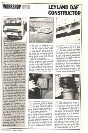
Almost all the troubles come from neglecting to lubricate the catches and make sure that the Bowden cables which operate them are not rusted and frayed. Unfortunately, being at the front of the vehicle, they are exposed to the elements, and need a regular dosing with heavy oil to keep them working easily and freely. At the back of the cab the hook for locking the cab in its down position is mounted on a threaded rod with adjusting nuts. Most cases of driver complaints of the cab's suspension not working properly can be traced to this hook not being adjusted properly, usually too slackly, so that the cab vibrates on its mountings.
Although there are setting figures for the hook, the easiest way to adjust it is by trial and error to reach the point where the locking bar engages firmly without being forced, yet does not fit so loosely on the hook that there is clearance. Too tight, and the cab may not lock properly. Too loose, and the cab will vibrate.
The hydraulic pump for raising and lowering the tilt cab is different from some British-made units in that, when the cab is down the control mechanism should be left with its pin in the vertical position. This is the "down" position of the pump.
If the control is left in the wrong position the hydraulic pressure could try to lift the cab against its locking hook. In extreme cases, it has been known for the cab to lock solid on its suspension to the point where its front mountings have fractured with vibration. The practice of "putting a bit of pressure" in the system to lock the cab against its hook must never be used. Many eight-wheelers operate in dusty conditions, and to prolong the life of the air filter the inlet trunking is carried up the back of the cab where it is less likely to suck in dust. The top part of the trunking tilts with the cab, and there is a flexible boot which sits on top of the filter inlet pipe when the cab is lowered.
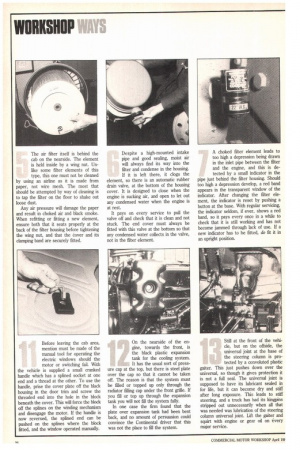
In cases of short filter life it invariably turned out that the flexible boot was not sitting properly on top of the inlet pipe. It had caught up and was distorted so that dust was being sucked into the filter. Always check the seating of this joint when you lower the cab. This company has come across several such cases. The air filter itself is behind the cab on the nearside. The element is held inside by a wing nut. Unlike some filter elements of this type, this one must not be cleaned by using an airline as it is made from paper, not wire mesh. The most that should be attempted by way of cleaning is to tap the filter on the floor to shake out loose dust.
Any air pressure will damage the paper and result in choked air and black smoke. When refitting or fitting a new element, ensure both that it seats properly at the back of the filter housing before tightening the wing nut, and that the Cover and its clamping band are securely fitted. Despite a high-mounted intake pipe and good sealing, moist air will always find its way into the filter and condense in the housing. If it is left there, it clogs the element, so there is an automatic rubber drain valve, at the bottom of the housing cover. It is designed to close when the engine is sucking air, and open to let out any condensed water when the engine is at rest.
It pays on every service to pull the valve off and check that it is clean and not stuck. The end cover must always be fitted with this valve at the bottom so that any condensed water collects in the valve, not in the filter element. A choked filter element leads to too high a depression being drawn in the inlet pipe between the filter and the engine, and this is detected by a small indicator in the
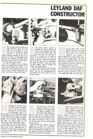
pipe just behind the filter housing. Should too high a depression develop, a red band appears in the transparent window of the indicator. After changing the filter element, the indicator is reset by pushing a button at the base. With regular servicing, the indicator seldom, if ever, shows a red band, so it pays every once in a while to check that it is still working and has not become jammed through lack of use. If a new indicator has to be fitted, do fit it in an upright position. The reservoir for the clutch hydraulic fluid lives under the front grille on the nearside. It is the usual type of translucent plastic reservoir, so the level can be checked without removing the cap. If topping up is necessary, it is important not to fill above the maximum level, mark otherwise fluid may be forced out of the reservoir on the clutch return stroke.
As well as making a mess, hydraulic fluid is an excellent paint remover, so be careful when topping up as there is not much room to tilt a container over the top of the reservoir. Before refitting the cap, make sure that the air hole in it is free. The clutch master cylinder is alongside the brake footvalve, and there is a bleed nipple at the back, to the side of the inlet union. The pipe run from the reservoir is downhill so, in theory, the air ought to bleed out by itself when you open the nipple. In practice, Channel Commercials has found that unless one man depresses the pedal and another opens and closes the bleed nipple, some air remains and results in a spongey clutch.
Both the clutch hydraulic pipes and the air pipes of the brake system are black plastic; they are not interchangeable but are marked "for clutch system" and "for braking system". On the other side of the radiator filler cap lives a small plastic reservoir labelled "Start Pilot". As its name suggests, this contains a highly volatile fluid to assist engine starting in sub-zero temperatures. Like the liquid gas in a cigarette lighter, the start fluid remains a liquid only as long as it is under pressure, so that the reservoir has to be topped up from an aerosol.
It is advisable to wear eye protectors when doing this as the unit is just about at eye level, and the gas often squirts out when the aerosol is applied or removed. It is also highly flammable, so do take care.
Before leaving the cab area, mention must be made of the manual tool for operating the electric windows should the motor or switching fail. With the vehicle is supplied a small cranked handle which has a splined socket at one end and a thread at the other. To use the handle, prise the cover plate off the black housing in the door trim and screw the threaded end into the hole in the block beneath the cover. This will force the block off the splines on the winding mechanism and disengage the motor. If the handle is now reversed, the splined end can be pushed on the splines where the block fitted, and the window operated manually. On the nearside of the engine, towards the front, is the black plastic expansion tank for the cooling system. It has the usual sort of press ure cap at the top, but there is steel plate over the cap so that it cannot be taken off. The reason is that the system must be filled or topped up only through the radiator filling cap under the front grille. If you fill or top up through the expansion tank you will not fill the system fully.
In one case the firm found that the plate over expansion tank had been bent back, and no amount of persuasion could convince the Continental driver that this was not the place to fill the system. Still at the front of the vehicle, but on the offside, the universal joint at the base of the steering column is protected by a convoluted plastic gaiter. This just pushes down over the universal, so though it gives protection it is not a full seal. The universal joint is supposed to have its lubricant sealed in for life, but it can become dry and stiff after long exposure. This leads to stiff steering, and a truck has had its kingpins stripped out unnecessarily when all that was needed was lubrication of the steering column universal joint. Lift the gaiter and squirt with engine or gear oil on every major service. Speaking of universal joints, but rather larger, the universals in the Constructor's drive line do not have sealedfor-life-bearings; there is a grease nipple on each yoke which should be lubricated at every service. On some vehicles which, like the vehicle we photographed, have automatic chassis lubrication fitted, the grease nipples on the universals are often neglected by fitters.
The nipples have to be quite small to allow the universal to work, and it is not always easy to get a lubrication line or ;rease gun on them unless the drive line s turned to bring them to their most txposed point. The reservoir for the powerassisted steering is on the nearside of the engine behind the radiator expansion tank, and is fitted with a dipstick so that the level can be checked without having to take the cap off. One reason for this, apart from ease of servicing, is that the system is sensitive to dirt, and the cap should be taken off only when topping up is necessary.
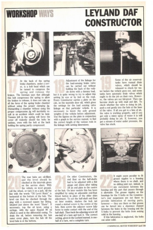
Make sure that any containers used for topping up are clean. As a secondary guard against dirt there is a filter in the reservoir underneath the filling cap, and this should be cleaned and washed off in clean fluid at major service intervals. Spring brake chambers on all wheels operate the S-cam brakes through manually set slack adjusters. Any falling-off in performance is usually traced to failure to check and set the adjusters. The adjustment is by a hexagon-headed bolt on the front which is locked by a sliding sleeve which has to be pushed back before a spanner can be applied. With the brakes off, the hexagon bolt should be turned until the push rod from the chamber is pushing towards the tdc of the slack adjuster's arm. If it is allowed to push beyond, efficiency falls off. Set and ensure the spring-loaded locking sleeve is back to the locked position. At the back of the spring brake chambers, under a cover, is a bolt head which can be turned to compress the spring and release the brakes. The foreman says that although this bolt compresses the spring to allow the brakes to release, it does not take up all the force of the spring brake chamber without using the proper clamping jig. Dismantling a chamber without using the proper compression jig will inevitably result in an accident which could be fatal. Tension left in the spring will force the cover off violently should the bolts be undone, even with the bolt at the back holding the spring partly compressed. Adjustment of the linkage for the load-sensing brake valve can be carried out without holding the back of the vehicle down with a dummy load,
but it is quite wrong to try to adjust this setting by eye or by feel on the road. Every Constructor carries a plate on the cab, on the nearside door sill, which gives the settings for the load sensing valve linkage on that particular vehicle. It is necessary to know the axle ground weights of the vehicle before adjustment. Use the figures on the plate in conjunction with a graph in the service manual, to find the correct length of the various rods in the linkage with setting dimensions.
Some of the air reservoir tanks have manual drain valves, which should be released to check for wa ter before the vehicle goes out, and some tanks have automatic drain valves which ought to do the job on their own. However, the valves are not fail-proof. They can become stuck up with mud and dirt. To check whether the valve is doing its job, push a rod gently into the hole at the base of the valve. If all you get is a hiss of air, the valve is working properly, and if you get only a misty spray of water it is still probably doing its job. If, however, you get a stream of water under pressure, the valve has stuck.
The rear hubs are oil-filled, and the level should be checked at the intervals given on the service sheet. With the vehicle on level ground, roll the wheel, or turn it on a jack, till the line with the words "Oil Level Horiz" is horizontal at the bottom of the hub. The level can then be checked through the plug with a recessed square bar fitting, situated just above the word "Horiz". If necessary, top the oil level, using a syringe, with the same Hypoid 90 oil which is used in the differential casing. To drain the oil, before removing the hub outer cover plate, turn the hub till the level hole is at the bottom. On older Constructors, the end float on the half-shafts had to be adjusted with a dial gauge and shims after taking off an end plate in the centre
of the hub. On later models this has been simplified by using an adjustable end-float thrust button in place of the older shim adjustment. To set the half-shaft end float on later models, slacken the lock nut round a slotted screw in the centre of the hub, then screw the adjuster screw fully home to make contact with the end of the half shaft. Then back the adjusting screw off one-half of a turn and lock it. The correct setting, given in the Leyland manual, is onehalf of a turn, not a complete turn.
It might seem peculiar to fit grease nipples to a housing where there is no shaft, and no sliding joint nor, indeed, is any movement between the housing and the part that passes through it allowable. The grease nipples on the housings for the U-bolts on the Constructor's rear suspension are not there to provide lubrication of moving parts, however — they are there so that grease can be forced into a clearance channel between the holes in the housing and the U-bolts to prevent the bolts from seizing solid in the housing.
If this lubrication is neglected, the bolts can seize solid.