


Improved Braking System
Page 62
If you've noticed an error in this article please click here to report it so we can fix it.
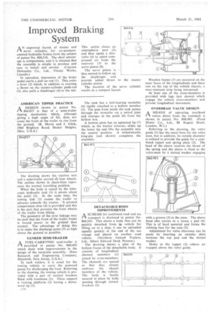
AN improved layout of master and 1.-1 servo cylinders for air-pressureassisted hydraulic brakes form the subject of patent No. 860,516. The chief advantage is compactness, and it is claimed that the assembly is simple to produce and
easy to install and service. (Clayton Dewa.ndre Co., Ltd., Titanic Works. Lincoln.) In operation, depression of the brake pedal exerts a pull on rod (1). This rocks a lever (2) which, in addition to exerting a thrust on the master-cylinder push-rod (3), also pulls a diaphragm (4) to the left. This action closes an atmospheric port (5) and then opens a discvalve (6) to admit compressed air from the reservoir (7) to the servo piston (8).
The servo piston is thus moved to follow up the diaphragm and provide added thrust to the master cylinder piston.
The location of the servo cylinder results in a compact layout.
AMERICAN TIPPER PRACTICE
ADESIGN shown in patent No. 860,027 is that of a semi-trailer tipping mechanism which, although giving a high angle of lift, does not cause the front of the trailer to rise from the ground. (R. Morse and J. Glick, 2960 Brighton Road, Shaker Heights, Ohio, U.S.A.)
The drawing shows the tractive uni and a semi-trailer carried oin four wheels The outline shown in chain-lines repre sents the normal travelling position.
When the body is raised by the telescopic hydraulic jack (1) it pivots about the point (2). At the same time, the towing link (3) causes the trailer to 'advance towards the tractor. 'A pivoted compression strut (4) is provided and this is the part that prevents the front wheels of the trailer from lifting.
The geometry of the strut linkage may be such that the front of the trailer frame is forced nearer to the ground than normal. The advantage of doing this is to make the discharge point (5) as high above the ground as possible.
TANKER SEMI-TRAILER •
PAA FUEL-CARRYING semi-trailer is described in patent No. 860,492 which deals with improvements in the design of the turntable assembly. (Esso Research and Engineering Company, Elizabeth, New Jersey, U.S.A.)
In such trailers, it is usual for the towing vehicle to carry the powered pump for discharging the load. Referring to the drawing, the towing vehicle is provided with a pair of vertical brackets fitted with trunnions (1). These support a rocking platform (2) having a downward lip (3).
c34 The tank has a ball-bearing turntable (4) rigidly attached to a hollow member (5). The pipe from inside the tank passes through the turntable via a swivel joint and emerges at the point (6) from the hollow box.
A bottom plate has an upturned lip (7) which, as the tractor reverses, slides up the lower lip and lifts the assembly into the central position. A withdrawable king-pin (not shown) completes the assembly.
DETACHABLE-BODY IMPROVEMENTS
ASCHEME for combined road and sea transport is disclosed in patent No. 860,543. This shows a body that can be quickly detached from it,s vehicle for lifting on to a ship; it can be unloaded equally quickly at the end of the sea voyage and placed on another road vehicle. (Northern Ireland Trailers, Ltd., Albert Edward Dock Preston.)
The drawing shows a plan of the bottom frame of the detachable body. It consists of longitudinal channel members (I) joined by cross-members. The channels are spaced so that they closely embrace the chassis members of the vehicle. The body is finally secured in place by bolts passing through slotted brackets (2). Wooden beams (3) are mounted on the inner faces of the longitudinals and these rest on the top of the vehicle chassis, a wear-resistant strip being interposed.
At least one of the cross-members is provided with tugs (not shown) which engage the vehicle cross-members and prevent longitudinal movement.
OVERHEAD VALVE DESIGN
r-k A MEANS of operating overhead
valves direct from the camshaft is shown in patent No. 860,983. (ford Motor Co., Ltd., 88 Regent Street, London, W.I.) Referring to the drawing, the valve guide (1) has the usual bore for the valve stem, but in addition, its outside diameter is utilized to provide the guide for a combined tappet and spring plate (2). The head of the sleeve receives the thrust of the spring and the sleeve is fixed to the valve-stem by a slotted washer engaging with a groove (3) in the stem. The sleeve head also carries in a recess a pad (4). This is of hard material and forms the rubbing face for the cam (5).
Adjustment for valve clearance can be made by inserting an annular shim between the top pad and the slotted washer.
Holes in the tappet • (2) relieve air trapped above the valve guide.