


Novel Features on Rear-engined Chassis
Page 60
If you've noticed an error in this article please click here to report it so we can fix it.
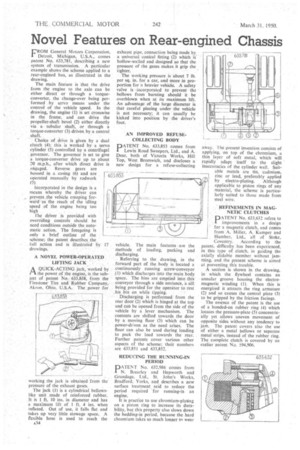
FROM General Motors Corporation, Detroit, Michigan, U.S.A., comes patent No. 633,781, describing a new system of transmission. A particular example shows the scheme applied to a rear-engined bus, as illustrated in the drawing.
The main feature is that the drive from the engine to the axle can be either direct or through a torqueconverter, the change-over being performed by servo means under the control of the vehicle speed. In the drawing, the engine (1) is set crosswise in the frame, and can drive the propeller-shaft bevel (2) either directly via a tubular shaft, or through a torque-converter (3) driven by a central shaft.
Choice of drive is given by a dual clutch (4); this is worked by a servo cylinder (5) controlled by a centrifugal governor. The governor is set to give a torque-converter drive up to about 20 M.p.h., after which direct drive is .engaged. Reverse gears are housed in a casing (6) and are operated manually by rodwork (7).
incorporated in the design is a means whereby the driver can -prevent ,the vehicle creeping forward-as the result of the idling
speed of the engine being too high The driver is provided with overriding controls should he need conditions outside the automatic action. The foregoing is only a brief outline of the scheme; the patent describes the full action and is illustrated by drawings.
A NOVEL POWER-OPERATED LIFTING JACK
A QUICK-ACTING jack, worked by I-1 the power of the engine, is the subject of patent No. 633,8.38, from the Firestone Tire and Rubber Company, Akron, Ohio, U.S.A. The power for
working the jack is obtained from the pressure of the exhaust gases.
The jack (1) is a cylindrical bellowslike unit made of reinforced rubber. It is 1. ft. 10 ins, in diameter and has a maximum lift of 1 ft, 4 ins, when inflated. Out of use, it falls flat and takes up very little stowage space. A flexible hose is used to reach the
exhaust pipe, connection being made by a universal conical fitting (2) which is hollow-walled and designed so that the pressure of the gases makes it grip the tighter.
The working pressure is about 7 lb. per sq, in, for a car, and more in proportion for a heavier vehicle. A safety valve is .incorporated to prevent the bellows from bursting should it be overblown when at its maximum lift. An advantage of the large diameter is that careful placing under the vehicle is not necessary; it can usually be kicked into position by the driver's foot.
AN IMPROVED REFUSECOLLECTING BODY PATENT No. 633,853 comes from Lewin Road Sweepers, Ltd., and A. Dear, both of Victoria Works, Hill Top, West Bromwich, and discloses a new design for a refuse-collecting
vehicle. The main features .are the methods of loading, packing and discharging.
Referring to the drawing, in the forward part of the body is located a continuously running screw-conveyor (1) which discharges into the main body space. The bins are emptied into this conveyor through a side entrance, a sill being provided for the operator to rest his bin on while tipping.
Discharging is performed from the rear door (2) which is hinged at the top and can be opened from the side of the vehicle by a lever mechanism. The contents are shifted towards the door by a moving floor (3) which can be power-driven as the need arises. The floor can also be used during loading to pack the load towards the rear. Further patents cover various other aspects of the scheme; their numbers are 633,851 and 633,852.
REDUCING THE RUNNING-IN PERIOD
PAUNT No. 632,986 comes from N. Brearley and Hepworth and Grandage, Ltd., St. John's Works, Bradford. Yorks, and describes a new surface treatment said to reduce the period required for running-in an engine.
It is practice to use ehromium-plating on a piston ring to increase its durability, but this property also slows down the bedding-in period, because the hard chromium takes so much longer in wear
away. 1 he present invention consists of applying, on top of the chromium, a thin layer of soft metal, which will rapidly adapt itself to the slight inaccuracies of the cylinder wall. Suit able metals are tin, cadmium, zinc or lead, preferably applied by electro-plating. Although applicable to piston rings of any material, the scheme is particularly suited to those made from steel wire.
• REFINEMENTS IN MAGNETIC CLUTCHES PATENT No. 633,632 refers to improvements in a design for a magnetic clutch, and comes from A. Miller, A. Kamper and Humber, Ltd., all of Stoke, Coventry. According to the patent, difficulty has been experienced, in this type of clutch, in guiding the axially slidable member without jamming, and the present scheme is aimed at preventing this trouble.
A section is shown in the drawing, in which the flywheel contains an annular groove housing the electromagnetic winding (1). When this is energized it attracts the ring armature (2) and so causes the central plate (3) to be gripped by the friction facings.
The essence of the patent is the use of a bonded-on rubber ring (4) which locates the pressure-plate (5) concentrically yet allows uneven movement of opposite sides without any tendency to jam. The patent covers also the use of either a metal bellows or separate metal strips, instead of the rubber ring. The complete clutch is covered by an earlier pa tent No. 594,906.