


A Petrol or Oil Engine at Will
Page 36
If you've noticed an error in this article please click here to report it so we can fix it.
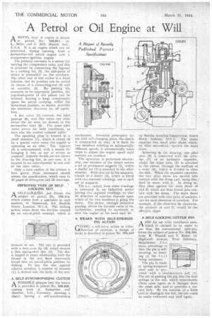
A NOVEL type of engine is shown PA in patent No. '558,851, by L. Miller and .C. Bell, Muncie, Ind., U.S.A. It is an engine which can be converted, during running, from a carburetter-led petrol engine into a compression-ignition engine.
The primary, necessity is a Means for varying the compression ratio, and this is achieved by connecting the big-end to a rocking bar (2), the mid-point of which is jOurnalled on the crankpin. The other end of this rocker is a fixed fulcrum, but its position can be varied by means of a connecting-rod (3) and
an eccentric (4). By . putting the. eccentric in its uppermost position, the top-dead-sentre of the 'piston Can be lowered, leaving a . large compression space for petrol .working, whilst the. lowermost position, as shown, provides the minimum clearance. for oil operation,.
A flat valve (7); controls the inlet passage (8), and this valve can close either the air inlet (as shown). or the carburetter inlet (8). The same inlet valve . serves for both conditions, as does also the central exhaust valve.
The sparking plug; is housed in :a small chamber (I ), which is closed off by a special valve when the engine -is operating as an oiler. ' The injector (5) is cam-operated, with a means' far bringing it into or out of action as required. Injector details are not shown in the drawing but, in one case, it is located in an ante-ctiamb0 to one side
of theinlet • valve. .
Only bare outline of the scheme is here given; those interested .should obtain the specification, whiCh runs to 17 pageS"of letterpress and 23 drawings..
IMPROVED TYPE OF SELFLOCKING NUT . ;
ASELF-LOCKING nut l'forms the subject of ,patent No, 558,414; which comes from a specialist in such
matters; Simmonds,. 2-3, Norfolk Street, London, W.C.2. The locking action arises from 'the friction created by. an . out-of-pitch • membcr, which is stressed in use. • The flat is provided with a bent-over lip (3) which secures a thin spring-steel disc (2). The disc is tapped in exact relationship with the thread in the nut, grind afterwards forced into an. out-of-pitchposition by dishing. To key the disc ,against relative rotation, a number of recesses (1) is dented into the body of the nut.
A SELF-SYNCHRONIZING CLUTCH
APOSSIBLE glimpse into the future is provided in patent No. 558,898, coming from A. Sampietro and Humber, Ltd., Coventry, showing a clutch having a self-synchronizing
mechanism. Intended principally for use With self-changing "gears, the °luta is constructed so that, if it finds its two Members roiating at kibstantially different speeds, it automatically takes steps to adjust the engine speed until matters are rectified.
. The operation is performed electrically; one member of the chitch carries a set of permanent 'magnets (1), whilst similar set CO is attached to the citlier memher. I3oth sets are in the Magnetic circuit of a'. stator (3), which is fitted with two separate windings, one 't each set of magnets. • •••
The ac. output from these windingS is conveyed to an induction Motor having two oppOsed Windings, so that its direction of rotation depends upon which of the two members is gbing the faster. The .motor, through reduction gearing, drives the throttle valve of the carburetter; tending to accelerate or slow the engine as the need maYbe.
A BRAKE WITH SELF-ENERGIZ ING ACTION
WING a self-servo action in either direction. of rotation, a design of brake is described in patent No. 558,443 byBehdix Aviation Corpetation, South Bend, Indiana, q1'.S.A. The, brake einploys two small pilot' shoes which, by their movement, operate the main shoes: .
Referring to the drawing, one pilot shoe (8) is connected with the cylinder (1) of an hydraulic expander, .whilst the other shoe (5) is attached to the piston, thrciugh the medium of a strut (3), which is divided to clear the aide. When the expander operates, ' the two pilot shoes are moved into .contact with the drum and, being free„ tend to move with it. In doing so, they abut against the main shoes (6 and 2) 'which are thus forced into contaCt with the drum_ The main shoes are provided with two pairs of anchors, • one for each direction of rotation. For, example, if -the direction be clockwise; the anchors (4 and 7) would be the
effective stops. . -• A SELF-LOCKING COTTER PIN
APIN for use with castellated nuts,. which is claimed to be easier to use than the conventional split-pin, forms the subject of patent No.' 558,500, fron-i R. Wassell and T. Rider; 11, Highcroft Avenue, West Didsbury,
Manchester. T h e
main advantage is 1558500
that the pin is selfsecuring, no bending of the tail being necessary.
• The pin is made of spring-tempered steel and is pro vided with a doubled-back tail (I). The act of pushing the phi into the hole springs in the tail, ,whicii immediately
clicks open again aS it emerges from the other side, and -so proVides a cer tain lock. By theexerciSe of a little #caie in closing:in the tail, the pin could be easily extracted and used 'again.