


USING ROAD SHOCKS To APPLY BRAKES O NE is' So accustomed
Page 46
Page 47
If you've noticed an error in this article please click here to report it so we can fix it.
to the seemingly unavoidable power wastage caused by converting the inertia or momentum of a moving vehicle into heat by the shocg absorbers and brakes, that no one appears yet to have explored the possibilities of utilizing the energy taken up by the former. That this can easily be collected and accumulated to do useful work is shown by a new hydraulic servo system brought out by the 'Alfred Teves Co., of Frankfurt-am-Main (Ate products) under the designation of Ate-Vago, the latter being the name of the inventor.
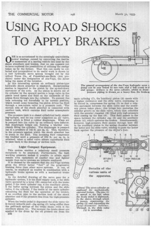
In this interesting system an ordinary piston-type hydraulic shock absorber is employed. Reciprocating motion is imparted to the piston by the up-and-down movement of the axle. As the piston is drawn out of Its cylinder by the upward motion a large valve in the piston bead opens and fluid on the underside of the piston flows through into the cylinder. To prevent the axle returning too forcefully to its normal position, which would cause bouncing, the piston drives the fluid through a non-return valve to a pressure tank. ' The suction side of the shock absorber is connected with another tank, which contains fluid under atmospheric pressure.
• The pressure tank is a closed cylindrical body, standineupright, and its top cover comprises an air valve, below which is fitted a rubber diaphragm. When air is pumped into the valve by an ordinary tyre inflator, this diaphragm bulges out, forming a bladder completely filling the cylinder. The diaphragm is pumped out to a pressure of 142 lb. per sq. in. This, therefore, is the pressure against which the shock absorber has to pump in the fluid. The incoming fluid compresses the bladder until a pressure of 570 lb. per sq. in. is attained, when a relief valve allows superfluous fluid to Pass back to the storage or suction tank.
Light Compact Equipment.
This system enables a relatively small pressure receptacle to be employed. Furthermore, the high working• pressure makes it possible to attain equal results with equipment of smaller size and lighter weight than servo systems as hitherto employed.
It is claimed by the makers that the Ate-Vago system gives the driver better " feel " of the progressive braking force than other servo systems. It can, of course, be employed as readily in combination with a hydraulic brake system as with a mechanical brake system.
In the detailed drawing of the servo gear for a hydraulic system, 1 is the fluid supply tank, 2 the slide valve operated by a lever (H) connected with the brake pedal, 3 the inner cylinder cap, 4 the auxiliary piston, 5 the buffer spring between the piston and the slide valve, 13 the cylinder, 7 the inside of the main cylinder containing the fluid for the operation of the brakes, 8 an overflow pipe to the suction tank of the shock absorber and 9 the pressure line from the high-pressure cylinder.
When the brake pedal is depressed the slide valve (2) is forced inwards and—th,e spring (5) being stiffer than the pull-back springs of the brake shoes—with it the auxiliary piston (4). The moment the brake shoes are applied to the drum by the oil pressed out from the B32
main cylinder (7), the auxiliary piston (4) meets with a higher resistance and the slide valve, continuing to be forced in, compresses the spring (5) so that a relative movement between the slide valve and the auxiliary piston takes place; this brings into operation the annular groove on the slide valve, which then coincides with the annular chamber (B) filled with high-pressure fluid coming up the line (9)'. This fluid passes to the space between the cylinder cap (3) and the auxiliary piston (4), which operates-the brakes. Simultaneously, however, high-pressure fluid passes through bore (E) in the auxiliary piston to the spring chamber between the latter and the slide valve, tending topush the latter back against the pressure of the driver's foot.
This back pressure is always directly proportionate to the actual brake force and gives the driver an exact Indication of the power being exerted. The feeling experienced by the driver is, in fact, exactly the same as if he were operating an efficient mechanical brake system, because the fluid being incompressible the connection with the brake shoes is virtually a rigid one.
When the pedal is released the fluid flows out through channels (E and F) into the hollow slide valve to the fluid chamber, whence it passes through the overflow pipe (8) back to the feed tank of the shock absorber.
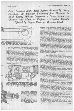
Interesting also is the arrangement adopted for the use of the Ate-Vago system in connection with mechanical brake gear. This is shown in another detail
drawing, which incidentally gives a good idea of the smallness of the unit. The slide valve (1) inside the long piston (3) is connected by a cross-shaft (2) and rods with the brake pedal. The cylinder is pivoted on the frame and the piston, the end of which protrudes from the cylinder, terminates in a disc (4) between which and the end of the slide valve is again arranged a spring (5). The piston end (4) is linked up with the mechanical brake system.
Upon the brake pedal being pressed down, the slide valve and piston travel a short distance together, as previously, until the progress of the piston is checked by the brake shoes coming into contact with the drums. The annular groove (6) in the slide valve then puts the cylindrical chamber (8) around the piston, containing high-pressure fluid, in communication with the pressure chamber (12) in the end of the cylinder. High pressure now operates on the large area piston and the smaller area slide' valve end with the same results as previously described. The return flow of the fluid goes through channel 11, -chamber 14 and pipe 15 to the feed tank of the shock absorber.
Durability of the Mechanism.
A criticism which comes to mind in connection with the combined shock absorber and pump is that the
repeated shocks imparted by the axle to the various joints and bearings of the link mechanism might cause unduly rapid wear. However, in view of the fact that
the parts are light, and that resistance is offered on only the -downward stroke, and then against an air cushion, there is justification for holding the view that the gear should function just as satisfactorily as the orthodox shock absorber.
Doubtless, too, it would be possible to make provision for adjusting the degree of restriction to the flow of fluid on the pressure stroke.
It will be observed that a pressure gauge is included in the system ; its purpose is to enable the driver to regulate the initial pressure in the cylinder, raised by a tyre pump. It will also indicate that the pressure in the system has been raised by the shock absorber to the figure at which the relief valve blows off. It might be desirable, however, to provide some means for adjusting this valve to suit variations in weight carried and in road surfaces traversed.
The pressure tank strikes us as a compact and simple means for attaining the desired end, having the addi tional advantage of being leakproof. One may, pre sumably, take it for granted that the material of which the diaphragm or bladder is composed is proof against any chemical reaction to which it might be subjected by the fluid, as would occur, for example, if certain oils and rubber were employed.
The elimination of time-lag in operating the brakes is an excellent point, and, although the energy is actually stored by compressing air, the medium of transmission is nowhere elastic.
The Ate-Vago servo system is not only applicable to the operation of brakes, but may also be used for steering and clutch servo or for opening and closing doom. It should have a big future for heavy oil-engined vehicles as these would no longer require engineoperated air pumps.