


REDUCING BRAKE GRIP ON CORNERS.
Page 28
If you've noticed an error in this article please click here to report it so we can fix it.
A Résumé of Recently Published Patent Specifications.
IT is well recognized that there is .always danger of skidding when 'a brake is applied while the vehicle is turning from the straight course. This is particularly the case with front wheels when on a wet road. It is true that all experienced drivers will release their brakes when turning, but, through forgetfulness or carelesaness, one may sometimes neglect to do so, with disastrous results.
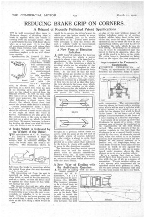
Specification No. 210,070 (C. Ileitrami) provides a means whereby front-wheel brakes will automatically, reduce their grip in agreement with a predetermined plan. According to this specification, t h e brake shoes_ are equipped with the usual expander cam, as shown above. A cam is provided, -in a direct line with the axis of the steering pivot, but should not move as the wheel is steered from the straight course. It will be seen that this cam is of an oval form, so that its major axis separates the brake shoes when following a direct course, but directly the wheels divert from that course the power of the brake is reduced.
Certain calculations seem to have been made so that the brake power should be relieved in some exact relation to the angle at which the wheel is turned. Calculations are also given for the correct form of the cam, so that it may act as a piVot on which the shoes can hinge. No means, however, is shown for keeping the shoes true with the drum when the brake is not in action.
A Brake Which is Released by the Weight of the Driver.
THE specification of C. E. 33urridge, No. 228,874, describes a brake in which there are springs under the driver's seat of sufficient strength to apply the brake when the seat is un occupied. The illustration shows, in full lines, the brake in operation, whilst the dotted lines show the seat depressed and the brake off.
The connecting rod from the seat is described as being provided with an elbow joint, or made of flexible material, such as a chain, so that the brake may be applied by either hand or foot without raising the seat.
The inventor does not say with what object he has designed this arrangement —whether it is to prevent the vehicle from running away when the seat is unoccupied, or whether it is to prevent theft. If it is for the latter purpose, we
are afraid-that it would not be very effi.
dent, as the first thing a thief would do n44 would be to occupy the driver's seat, in which case the brakes would be automatically released, just as he would want them to do. Unless some device were arranged to lock the brakes off, such a vehicle• would be inconvenient when being pushed about in a garage.
A New Form of Direction Indicator. A NEW foreof indicator for showing the direction in which a motor vehicle is about to travel is described in specification No. 228,979 )(0. Thistlethwaite). In this invention a plate is provided which can be attached at the year of a vehicle. Attached to this plate is a central bar, as shown in both views. At the ends of this bar four movable pieces are pivoted so that they can lie either as shown in the upper view, which indicates that the vehicle is going to continue in a straight course, or they can be moved so that they take the form shown in the lower view, which forms an arrow pointing to the right, which indicates that the vehicle is about to follow that direction, whilst-the movable pieces can, when desired, be
b Sought to a position which forms an a Tow, with its point at the left end of the shaft, which, of course; indicates that the vehicle is about to go in that direction. The movable pieces are pivoted at a point about that indicated by the letter A. which will enable them to move in the directions required.
The inventor describes several means which may be used for moving the pieces, such as electric connections, Bowden wires, etc. In some eases the centre bar is made to slide, and, in doing so, actuates the pieces'ielaich alternately form the head or tail.
A New Way of Dealing with the Anti-dazzle Question. A MEANS of dealing with the anti
dazzle problem is disclosed by H. P. Earnshaw, o f t Ii e 'United States, in specification No. 229,175. The inventor proposes to fix a third lamp, as shown in the accompanying illustration, Which will shine on or near to the kerb. This is said to enable the driver, when meeting another vehicle, to keep over towards the kerb or edge of the road vvithout danger of hitting telephone pests or of getting ditched, whilst, being fixed to the body of the car, near the rear, its rays are shielded by the car from the view of any approaching vehicle, provided the driver is hugging the kerb, which he can do with safety. In looking at the illustration, it must be remembered that the patent is drawn in America, where the rule of the road is to drive on the right. The extra lamp is described as being fitted on the top of the rear mudguard.
Improvements in Pneumatic Suspension.
GIUSEPPE PELLEGRINO, of Turin, in specification No. 229,207, describes an improved .form of pneu
matic suspension. The accompanying drawing shows the front axle in section, above which will be seen a cylinder with a cover bolted to it, which acts as a guide for the plunger (A) which is fixed to the frame. At the lower end of this plunger is an enlargement in the form of a plate bearing on a flexible diaphragm.
A pressure of air is kept up under the diaphragm by means of a pump. This pressure can, of course, be regulated to the requirements of the load being carried. The special feature of the invention consists in the tat= that the diaphragm is so arranged that it is supported by the cover, as shown in dotted lines, when the piston is in its highest position, and the deformation of the diaphragm as the piston descends is a gradual one, the diaphragm being relieved from strains to some extent by the manner in which it lies against the cover of the cylinder. Air can be maintained under pressure .above the diaphragm so as to give a snubber effect.
It is a curious fact that so little 8hould have been done lately in connection with the use of air as a means of suspension. We can recollect riding on a car sprung with compressed air in cylinders fitted with pistons in 1907, and we have always considered that this was the best system we have ever tried.