


A PETROL-ELECTRIC BUS FOR PHILADELPHIA.
Page 10
Page 11

If you've noticed an error in this article please click here to report it so we can fix it.
An Interesting Type of Chassis Which Embodies a Six-cylinder Engine, a Generator of the Exciter Type and Separate Motor Drive to Two Undersiung Worms. '
TN VIEW of the enormous develop-. 1..ment of passenger transport by motor .omnibuses in America, the types of chassis employed are of considerable interest. We have on previous occasions alluded to many of these, including multi-wheel machines, and it has been known by us for some time that experiments have been in progress with petrol-electric bus chassis.
The Philadelphia Rural Transit Co., having placed a large order for petrolelectric chassis with the Yellow Coach Manufacturing Co., of Chicago, the latter have developed what is known as their " Z" type, in which the leading features are simplicity of control, changes of speed dependent entirels, upon the position of the throttle (so that the driver need not remove his hands from the steering wheel except in cases of emergency or when the electric brakes are applied on a long hill), and smooth and rapid acceleration.
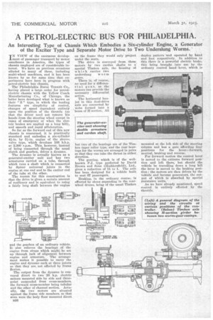
So far as the forward end of this new chassis is concerned, it is practically standard and embodies a six-cylinder 4k-in. by 51-in. engine of the sleeve-, valve type, which develops 108 b.h.p. at 2,200 r.p.m. This, however, instead of being connected through the usual clutch and gearbox, drives a dynamo.
The dynamo is actually known as a generator-exciter unit and has two armatures carried on a tube, through which runs a shaft which is connected by Spicer universal joints to the engine at one end and to the exciter end of the tube at the other.
The reason for this construction is that the drive is given a certain amount of resiliency and is equivalent to using a fairly long shaft between the engine and the gearbox of an ordinary vehicle. It also relieves the bearings of the engine from stress which might be set up through lack of alignment between engine and armature. The arrangement makes it possible to carry the engine and dynamo each at three points so that they are not affected by frame flexion.
The output from the dynamo is conveyed direct to two 20 h.p. electric motors mounted side by side and threepoint suspended from cross-members, the forward cross-member being tubular and the other of channel section. Actually, the two motors are situated against the frame side members, so that even were the body floor mounted direct B26 on the frame they would only project under the seats.
• The drive is conveyed • from these, motors by two cardan shafts to a special Timken axle, the housing of which carries two underslung worm „gears.
There is, of course, no need for a differential gear, as the motors can provide the necessary differential action.
The horizontal banjot in this dual-drive axle are connected by , webs formed into a beam of if section. All but two of the bearings are of the Timken taper roller type, and the rear bearings for the worms are arranged in pairs so that they can take the thrust in either direction.
The gearing, which is of the wellknown F.J. type perfected by David Drown and Sons (Huddersfield), Ltd., gives a reduction of 11 to 1. The axle has been, designed for a vehicle built to seat 67 passengers.
Braking, in the ordinary course, is effected by shoes expanding in the rearwheel drums, being of the usual Timken duplex pattern and operated by hand and foot respectively. In addition to this there is a powerful electric brake, this being brought into use by the ordinary control hand lever, which is mounted at the left side of the steering Column and has a gate affording four positions for the lever—forward, neutral, braking and reverse.
For forward motion the control lever is moved to the extreme forward position and left there, but should the vehicle be travelling down a long hill the lever is moved to the braking position; the motors are then driven by the vehicle and become generator, the output of which is absorbed by special resistance units.'
As we have already mentioned, speed control is entirely effected by the throttle. A 12-volt battery is used in connection with the conventional two-unit starting and lighting system, and this battery also serves to supply field current to the exciter and the dynamo and current for the ignition. When starting the vehicle, the driver switched on the ignition and closes the starter switch in the ordinary manner. This same action sends battery current into the exciter field. When stopping, switching off the ignition also opens the circuit of the exciter field and so prevents discharging of the battery.
When the engine starts the exciter picks up immediately and, in addition to the coil for the battery current, each exciter field carries a coil for selfexcitation and a portion of the current developed by the exciter flows through this coil. The major portion, however, passes through the field coils of the dynamo, which is not self-exciting, having no shunt Circuit across its mains.
The dynamo is provided with a differential series winding, which serves the purpose of limiting the load on it as the load on the motors increases. For instance, when the vehicle commences to climb a hill, the motors draw more 'current to develop the necessary torque, but less voltage is necessary because the speed of the vehicle decreases. The reverse-series winding lowers the voltage as the demand on the current is increased and thus tends to keep the output constant for a given engine speed. The motors are of the series-wound type. When arranged for electric braking, the field coils are reversed, and the motors tend to reverse. In order that this action may not be too severe, the two motors and the resistance are all connected in series across the generator terminals.
The rate of acceleration depends on the characteristics of the dynamo and motors, and smooth operation, therefore, is not so dependent on the skill of the driver. Another advantage is that the engine cannot be stopped unintentionally, for the reduction in engine speed merely allows the engine to idle, as no appreciable current is delivered. The same action makes it impossible to race the engine unless the control lever is placed intentionally in the neutral position. The electrical connection of the two driving motors, which are in parallel when running forward and in series when running in reverse, gives the effect of a locked differential, which is specially advantageous in winter -when wheel-slip may occur.
The dynamo and each of the motors are supported by three bolts and can be lowered very quickly into a pit for inspection or repair.
The frame is inswept slightly towards the front, humped over the rear axle and extended to carry the tonduetees platform. It is very low, the top of the frame being only 20 ins, above the road' surface when under full load. The side members are over 30 ft. long.
The clearance under the worm housings is 7t ins, and under the lowest points of the motor housings 71 ins. The worm centres are 27 ins, apart, and the track at the front is 6 ft. 2/ ins.— rather more than usual—in order to give a shorter turning radius an the long wheelbase, which is actually 19 ft.2 ins. • The chassis is designed for carrying a double-deck body to seat 67 persons.