


road and workshop
Page 41
If you've noticed an error in this article please click here to report it so we can fix it.
y Handyman
6enchvvise: Lathe sense (24)
HE main problem for the lathe machinist not the actual turning, boring or facing peration, but the one of mounting the item; . is an old-accepted rule that if you can taunt the work, the lathe will do the rest. This, however, has to be put across to he trainee in such a way that it will not limit im in his approach to the vast range of nark that can be accomplished in the lathe. le may think that if a work piece cannot be eld in a chuck or on a faceplate, between entres or secured to a vertical slide when is is available, then there is little more the ithe can be expected to do; his tendency rill be to say: "Sorry, not possible".
But in earlier days with a far smaller ariety of machine tools available, the arner had to be very versatile. However, lthough one man may see a possible way I mounting a difficult item, yet another qually skilled turner capable of top-class recision work may not see any approach 3 a particular mounting problem, if onventional methods are not applicable.
10 pattern Therefore, in order to score at all, the arner on vehicle reclamation work today lust not be tied by any sort of hard and ast rules. Whereas many jobs follow a flown pattern, more and more jobs do not. t now becomes a case of first: can the lathe la the actual work called for? The second uestion is: can I find a reliable means of aounting the work?
Once this outlook has been accepted and a few somewhat unconventional methods demonstrated, the trainee begins to think for himself. Whereas turning work is, of course, limited by the capacity of the lathe since the work must revolve, boring, milling and shaping are not tied to such limits, as the work is stationary; therefore, the only question is: can the tool reach the area of work?
Obviously, work can be bolted to the face of a top slide or cross slide, and I have already described how a diff carrier was dealt with. Again, when a differential casing for a worm drive unit had to be rebored in the bearing apertures, a two-week queue, in the local machine shop compelled me to look again at the lathe—the only machine available. First glance was enough to show that the bearing housings would be standing too high, even with the casing.standing flat on the ways, and the alternative of standing the casing upside down on the ways looked impossible as there was no flat face at all, only the rounded shell of the worm casing.
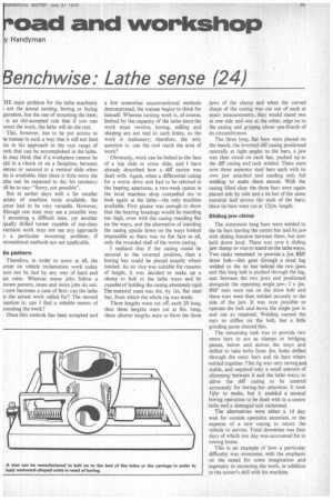
I realized that if the casing could be secured in the inverted position, then a boring bar could be placed exactly where needed. As no vice was suitable for reasons of height, it was decided to make up a clamp to bolt to the lathe ways and be capable of holding the casing absolutely rigid. The material used was 4in. by lin. flat steel bar, from which the whole rig was made.
Three lengths were cut off, each 2ft long, then three lengths were cut at 8in. long; these shorter lengths were to form the three jaws of the clamp and when the curved shape of the casing was cut out of each at exact measurements, they would stand two at one side and one at the other, edge on to the easing and grippng about one-fourth of its circumference.
The three long, flat bars were placed on the bench, the inverted cliff casing positioned centrally at right angles to the bars, a jaw was then stood on each bar, pushed up to the cliff casing and tack welded. There were now three separate steel bars each with its own jaw attached and needing only full welding to make them secure. With the casing lifted clear the three bars were again placed side by side and a tie bar of the same material laid across the ends of the bars; these tie bars were cut at 12+in. length.
Sliding jaw clamp The outermost long bars were welded to the tie bars leaving the centre bar and its jaw with sliding freedom between them, but now held down level. There was now 'a sliding jaw clamp or vice to stand on the lathe ways. Two tasks remained: to provide a +in. BSE draw bolt—this goes through a stout lug welded to the tie bar behind the two jaws and this long bolt is pushed through the lug, sent between the two jaws and positioned alongside the opposing single jaw; 2 x BSE nuts were run on the draw bolt and these nuts were then welded securely to the side of the jaw. It was now possible to operate the bolt and move the single jaw in and out as required. Welding caused the nuts to stiffen on the bolt, but a little grinding paste cleared this.
The remaining task was to provide two more bars to act as clamps or bridging pieces, below and across the ways and drilled to take bolts from fin. holes drilled through the outer bars and tie bars where welded together. This rig was very strong and stable, and required only a small amount of shimming between it and the lathe ways, to allow the diff casing to be centred accurately for boring-bar attention. It took 5+,hr to make, but it enabled a normal boring operation to be dealt with in a centre lathe and a damaged unit reclaimed.
The alternatives were either a 14 day wait for outside specialist attention, or the expense of a new casing to return the vehicle to service. Total downtime was four days of which one day was accounted for in towing home.
This is an example of how a particular difficulty was overcome, with the emphasis on the neeed for some imagination and ingenuity in mounting, the work, in addition to the turner's skill with his machine.