


A Novel Two -speed Wheel
Page 58
If you've noticed an error in this article please click here to report it so we can fix it.
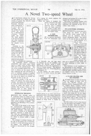
AN unorthodox scheme for driving the wheels of a vehicle forms the subject of patent No. 693,374, which comes from National Research Development Corporation, 1 Tilney Street, London, W.I. In this design the road wheels are driven by a self-contained oil-motor housed inside the wheel. The chief purpose is for use on tractors and other machines needing a powerful but usually slow speed.
Attached to the wheel are five spaced cylinders (1), the whole assembly running on ball-bearings carried by the stationary axle. The axle also carries an eccentric (2) to which all the pistons of the five cylinders are connected.
The hydraulic circuit comprises central-flow and return pipes which lead to a rotary valve (3) from which pipes run to the cylinder-heads. The use of five cylinders ensures that one or more is always on the power stroke, thus rendering the unit self-starting as soon as hydraulic pressure is applied. To reverse the direction of running, all that has to be done is to reverse the direction of flow of the oil.
The main novelty is the use of a sleeve (4) between the piston and the cylinder. By means of a small hydraulic catch (not shown) the sleeve can be locked to either the piston or the cylinder, thus giving a choice of two different sizes of bore, giving the equivalent of a two-speed gearbox.
6g3.374 HYDRAULIC BRAKING
PATENT NO. 693,488, refers to hydraulic brakes in which a small residual pressure is maintained in the system at all times, being intensified when actual braking is needed. The patentee is A. Barbisan, 6 Via Lovanio, Milan, Italy.
The basis of the patent is the means for automatically maintaining this tesidual pressure in spite of the inevitable small leakages. The main piston (I) which is shown in its inoperative position, uncovers a small port (2). This does not communicate with the reservoir, but leads to an upper cylinder (3) which is always under a slight pressure.'
The pressure is present because the far side of the piston (4) is connected, via pipe 5, to the lubricating system of the engine. The magnitude of the pressure is determined by the strength • a40
of a spring (6) which opposes the engine-oil pressure.
When the engine is stopped, the
it is desirable that the gap ' shall be constant for all the cylinders, and patent No. 693,383, shows a modified design in which this requirement is met in a simple manner. The patentee is Joseph Lucas, Ltd., Great King Street, Birmingham, 19.
In this scheme, the rotor carries a metal bar (I) which receives the high-.
tension charge at its centre and closely approaches each of the output electrodes (2) in turn. So much is commox) practice, but in this case the rotating bar, instead, of being fixed, is loaded by plungers and springs (3) so that it abuts against the central electrode.
This gives it a definite location with respect to the distributot body and so maintains the required air-gap (4) to within close limits.
PIN-AND-WORM STEERING
IMPROVEMENTS in worm-type steering boxes are shown in patent No. 692.496, which comes from R. Bishop and R. Johnston, Flowton Priory, Harpenden, Hens. The patent refers to the type of box in which the
worm follower is a pin, or pins.
The drawing shows the worm and the engaging pins (I and 2), which swing about the centre of the rocker shaft (3). The groove width of the worm is not constant, but widens towards the ends. About the straightahead position, the pins are a good fit in the worm, but at other positions a little slack is present.
This, however, is not considered to be detrimental to the working. The right-hand pin is made a little smaller than the other, and their operative faces are slightly convex, the worm flanks being concave to suit.
A FLAME HEATER FOR OIL ENGINES
AFLAME heater to assist in starting an oil engine, is dealt with in patent No. 691,993 (AIcock and Ricardo and Co., Engineers*(1927) Ltd., Gt. Suffolk Street, London, S.W.1).
The drawing shows a typical arrangement for a four-stroke engine. To the main air intake (1) is attached a chimney (2) at the bottom of which is a small wick lamp (3). In .the upper part is a partition (4) formed of several layers of metal gauze. This is heated by the flame. and is then turned into position 5 in which it covers the air inlet.
The first intake of air is thus heated by the hot gauze and enables a, ready start to be made. Once the engine is running, the gauze flap is swung away.