


Low-pressure
Page 36
If you've noticed an error in this article please click here to report it so we can fix it.
njection
valve Opening
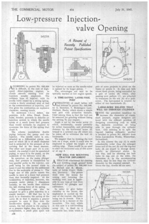
A CCORDING to patent No. 545,559 tilt is difficult, in the case of highspeed direct-injection engines, to obtain smooth running with the injectors usually employed. The ordinary type of injector, with its needle valve closed by a strong 'spring, creates a finely atomized mist of fuel at the commencement of injection, and this gives the combustion an explosive character, causing knock.
To surmount this defect, the patentee, A.B. Atlas Diesel, Stockholm, Sweden, proceeds to describe an injection system in which the needle opens at a much lower fuel pressure than would normally be required to overcome the force of the spring that closes it.
The scheme necessitates double piping between the pump and the injector. The needle valve is constructed as a differential piston, one part of which (3) is of small diameter and is subjected to the pressure of the arriving fuel in the usual manner. The other and larger part (1) is. connected, via conduit 4 and its associated piping, to space 5 in the pump, on the underside of the delivery valve (6). In operation, as the pump plunger rises, fuel pressure is transmitted by two parallel paths to the injector, one path being by the normal route to space 2 and the other by the additional line to the underside of piston 1. The larger size of this piston causes the needle to open at a lower fuel pressure than that normally required. At the termination of injection, however, the pressure under piston 1 disappears entirely, so the needle then receives the. full closing force of its spring.
The arrangement can also be adapted to give a pilot injection in a simple manner, 'All that has to be done is to dimension the spring of the valve (6) so that it requires a greater pressure to open it than does the needle-valve spring. If, as usually occurs, the fuel stored in the piping is at a pressure higher than the cylinder compression, a small pilot spurt will
be injected so soon as the needle-valve is opened by its larger piston. The advantages are said to be specially marked at low engine speeds.
A TIME-SAVING LATHE-TOOL
OP"ATIVES of small lathes will find interest'in patent No. 545,568, by A. Saunders, 7, Brokengate Lane, Denham, Bucks, which shows a simple tool post with attractive features. Chief among these is that the tool can be removed for grinding without losing the setting, In any respect. Angle is set by the under screw (1) which, incidentally, would'probably be rather inaccessible, and protruding distance by the horizontal screw (2) housed in a screwed cap (3) which can be taken off to withdraw the tool (4) backwards.
We suggest that by forming the tool hole on a slope, screw 2 could also be employed to adjust the height of the cutting edge. There would be no need to alter the horizontal axis of this screw or of cap 3.
• NEW IDEA FOR MOUNTING TRACTOR IMPLEMENT
A TRACTOR attachment for clearing .1-1 and leyelling_rough ground forms the subject of patent No. 545,593 from R. Barrall and E. Moore, both of Little Court, Helldon, Daventry. The patent deals with the means for raising and lowering the Working tool, and is applicable ter any type of tool from bull-dozers to ploughs and
cultivators. •
In order to give better visibility to the driver, the implement is carried on the rear of the tractor, the latter being run in reverse. This is stated to he a feature of the invention. The tool, which in this case is a soil-levelling . scoop (4), is fixed to a transverse bar, from which a pair of arms projects to pivot on the frame at points 3. It rises and falls about these pivots, being controlled by a pair of cables (6) which, after passing over pulleys (1), are attached• to. trunnions on the nut (5) of a jackscrew. The last-named is rotated by either of two handwheels (2).
LARGE-BORE BIG-END THAT WILL GO THROUGH CYLINDER
WITH the prevalent tendency to W increase the diameters of crankshaft journals, engine designers are faced With the difficult problem of designing connecting rods to fulfil the desirable condition of being able to pass through the, cylinder bore. One solution is to split the big-end bearing obliquely; another is detailed in patent No. 545,011 from Swiss Locomotive Works, Winterthur, Switzerland.
In this scheme the cap (1) is made considerably wider than the enlarged lower end of the rod (2) and the big-end bolts (3) are sloped to diverge downwardly, as illustrated above. In this way, aud by allowing the bolt holes to run out at the sides, the dimension A, in the accompanying sketch, may be less than the cylinder diameter by the required amount. To.., locate the cap, dowels (4)' are used.